Cylinder block bore hole seam allowance end face bouncing degree and flatness gauge

A technology of end face runout and cylinder block, which is used in mechanical roughness/irregularity measurement, mechanical clearance measurement, etc., can solve the problems of large measurement error and troublesome measurement, and achieve the effect of simple structure and improved inspection efficiency.

Inactive Publication Date: 2017-11-07
GUANGXI YUCHAI MASCH CO LTD
6 Cites 0 Cited by

AI-Extracted Technical Summary

Problems solved by technology

[0005] The purpose of the present invention is to propose a method that can quickly and accurately measure the end face runout and flatness detection of the small plane of the cylinder bore seam of the cylinder block,...

Method used

A kind of checker of cylinder block cylinder hole spigot end face beating degree and flatness, comprising support shaft 3, guide stub 4, measuring tool, table frame 2, guide stub 4 is combined in support shaft 3 lower ends, also includes The taper reference plate 1 and the table frame 2 are combined on the upper end of the support shaft 3; The measuring tool is a dial gauge and is assembled on the right end of the meter frame 2, and the dial gauge measuring head points to the cylinder bore spigot plane and can be in contact with the spigot plane. The diameter of the guide stub 4 is substantially the same as the measured diameter of the lower cylinder bore of the cylinder block. The upper surface of the taper reference plate 1 is a horizontal reference plane, and the flatness of the small plane of the notch can be measured by using the reference plane together with the auxiliary table frame; the diameter of the upper surface of the taper reference plate 1 is larger than its lower surface, which is convenient for measurement.
Further, support shaft 3 is a stepped shaft, and this stepped shaft is divided into shaft I31, main shaft 32, shaft II33, taper shaft 34 from bottom to top; Guide short post 4 is a central hollow cylinder; Taper reference plate 1 is Hollow round platform in the mid...

Abstract

The invention discloses a check tool for the runout and flatness of the end surface of the cylinder hole spigot of a cylinder block, which includes a support shaft, a guide stub, a measuring tool, and a gauge frame. The guide stub is combined with the lower end of the support shaft, and further includes A taper reference plate, the meter frame is combined on the upper end of the support shaft; the taper reference plate is combined on the upper part of the support shaft and between the meter frame and the guide short column; the measuring tool is assembled on the End of watch stand. The inspection tool has a simple and compact structure, can quickly and accurately detect the runout and flatness of the end face of the cylinder bore seam of the cylinder block, ensures stable and controlled product quality, and improves inspection efficiency.

Application Domain

Mechanical clearance measurementsMechanical roughness/irregularity measurements

Technology Topic

EngineeringCylinder block +1

Image

  • Cylinder block bore hole seam allowance end face bouncing degree and flatness gauge
  • Cylinder block bore hole seam allowance end face bouncing degree and flatness gauge
  • Cylinder block bore hole seam allowance end face bouncing degree and flatness gauge

Examples

  • Experimental program(1)

Example Embodiment

[0022] The present invention will be further described in detail below in conjunction with specific embodiments and with reference to the drawings. It should be emphasized that the following description is only exemplary, and is not intended to limit the scope of the present invention and its application.
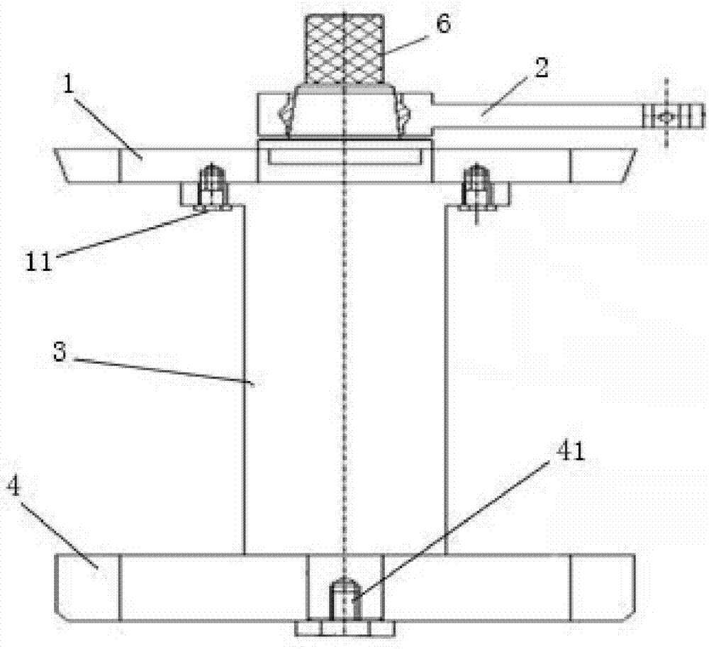
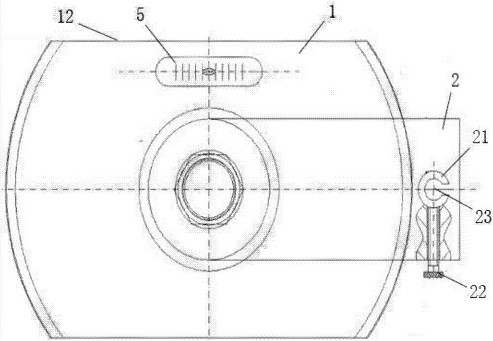
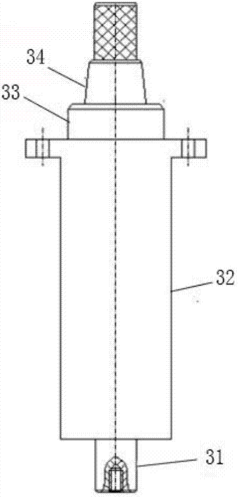
[0023] A test tool for the runout and flatness of the end face of the cylinder bore of a cylinder block, comprising a support shaft 3, a guide short column 4, a measuring tool, and a meter frame 2. The guide short column 4 is combined with the lower end of the support shaft 3 and also includes a taper reference plate 1. The meter frame 2 is coupled to the upper end of the support shaft 3; the taper reference plate 1 is coupled to the upper part of the support shaft 3 and between the meter frame 2 and the guide stub 4. The measuring tool is a dial indicator and is assembled on the right end of the meter frame 2. The dial indicator probe points to the stop plane of the cylinder bore and can be in contact with the stop plane. The diameter of the guide stub 4 is basically the same as the measured diameter of the lower bore of the cylinder block. The upper surface of the taper reference plate 1 is a horizontal reference surface, and the flatness of the spigot facet can be measured by using the reference surface and the auxiliary meter frame; the diameter of the upper surface of the taper reference plate 1 is larger than the lower surface, which is convenient for measurement.
[0024] In a preferred embodiment, it further includes a level 5, and a horizontal sink is provided on the upper surface of the taper reference plate 1; the level 5 is assembled in the horizontal sink. The level 5 is embedded on the taper reference plate 1 to ensure that when the bubble of the level 5 stays at the middle position of the scale line, the upper surface of the taper reference plate 1 is in a horizontal state. At this time, the upper surface of the taper reference plate 1 and the bracket should also be ensured The central axis of the shaft 3 is vertical.
[0025] Furthermore, the support shaft 3 is a stepped shaft, which is divided into a shaft I31, a main shaft 32, a shaft II33, and a tapered shaft 34 from bottom to top; the guide stub 4 is a hollow cylinder in the middle; the taper reference plate 1 is a hollow truncated cone in the middle The table frame 2 is a pendulum rod, the left part of which is provided with a taper hole matching the tapered shaft 34, and the right end is provided with a positioning hole 23 for assembling a dial indicator. The inner wall of the positioning hole 23 is equipped with an opening copper sleeve 21, a dial indicator sleeve The cylinder is placed in the open copper sleeve 21 and the open copper sleeve 21 is pressed with a locking bolt 22 to pre-tighten the dial gauge. The purpose of using the open copper sleeve 21 is to prevent the locking bolt 22 from being directly squeezed onto the dial gauge sleeve to cause deformation and damage the dial gauge. The taper hole and taper shaft 34 are processed by grinding to ensure a good fit, and it can ensure that the watch frame 2 does not move up and down or swing during the rotation. The taper reference plate 1 is a truncated cone structure, which reduces the contact area between the side of the taper reference plate 1 and the cylinder hole, which is beneficial to the level correction of the taper reference plate 1; the diameter of the upper surface of the taper reference plate 1 is 1mm larger than the diameter of the cylinder hole on the cylinder block. The diameter of the lower surface is 3mm smaller than the diameter of the upper cylinder hole.
[0026] Further, the shaft I31 is in transitional fit with the center hole of the guide stub 4, a screw hole is opened at the lower end of the shaft I31, and the guide stub 4 is locked on the shaft I31 with a flange bolt 41; the shaft II32 is connected to the center hole of the taper reference plate 1. For transitional fit, the main shaft 32 is provided with an ear shoulder, and the flange face bolt 11 passes through the ear shoulder and is screwed into the taper reference plate 1 to lock it. The center of the guide stub 4, the taper reference plate 1, and the support shaft 3 are coaxial.
[0027] Further, the taper reference plate 1 has a flat position 12 cut off in the axial direction, the guide is short, and 4 also has a flat position similar to the taper reference plate 1.
[0028] Further, it also includes a handle 6 which is coupled to the upper end surface of the bracket shaft 3.
[0029] Furthermore, the watch frame 2 is stepped, thick on the left and thin on the right. The purpose is that the center of gravity of the watch frame 2 is at the left end, and the left end is designed with the support axis 3.
[0030] How to use this inspection tool:
[0031] 1) Perform metrological verification of the inspection tool before use, and use it only when the design requirements are met;
[0032] 2) When performing the measurement, remove the front and burrs from the inspected part, then place the inspection tool in the cylinder hole to be measured, install a dial indicator, adjust the inspection tool, and make the bubble of the level 5 stay on the scale line In the middle, when the upper surface of the taper reference plate 1 is in a horizontal state and the axis of the bracket shaft 3 coincides with the central axis of the cylinder hole, the end face runout measurement of the small plane of the cylinder hole stop can be performed, and the meter frame 2 is around the bracket axis 3 taper shaft 34 rotates once, and the end face runout of the small plane of the cylinder hole stop can be measured;
[0033] 3) Then use the auxiliary gauge base and the dial indicator, the bottom of the auxiliary gauge base is closely attached to the upper surface of the taper reference plate 1, the dial indicator probe is in contact with the small surface of the stop, the dial indicator is adjusted to zero, and the position is even Layout points to measure the flatness of the spigot, move the auxiliary gauge base to make the dial gauge probe move in the radial direction of the axis 3 of the bracket shaft within the width of the spigot facet, you can measure the data, and then turn the gage 90 degrees , Adjust the upper surface of the taper reference plate 1 of the level gauge again, measure the flatness by the same method, and finally obtain the flatness of the spigot facet through data processing.
[0034] Those skilled in the art will recognize that it is possible to make many modifications to the above description, so the embodiments and drawings are only used to describe one or more specific implementations.
[0035] Although the exemplary embodiments regarded as the present invention have been described and described, those skilled in the art will understand that various changes and substitutions can be made thereto without departing from the spirit of the present invention. In addition, many modifications can be made to adapt a specific situation to the teachings of the present invention without departing from the central concept of the present invention described herein. Therefore, the present invention is not limited to the specific embodiments disclosed herein, but the present invention may also include all embodiments and their equivalents falling within the scope of the present invention.

PUM

no PUM

Description & Claims & Application Information

We can also present the details of the Description, Claims and Application information to help users get a comprehensive understanding of the technical details of the patent, such as background art, summary of invention, brief description of drawings, description of embodiments, and other original content. On the other hand, users can also determine the specific scope of protection of the technology through the list of claims; as well as understand the changes in the life cycle of the technology with the presentation of the patent timeline. Login to view more.

Similar technology patents

Body condition measuring device

InactiveUS20050234351A1simple structure
Owner:DENSO CORP

Magnetic cooling apparatus and control method thereof

ActiveUS20130180263A1simple structure
Owner:SAMSUNG ELECTRONICS CO LTD

Dual-Drivetrain of Power-Assist Vehicle

InactiveUS20100181130A1enhance uphill momentumsimple structure
Owner:CHOU WEN CHENG

Classification and recommendation of technical efficacy words

  • Simple structure
  • Improve inspection efficiency

Sharing system for air-conditioning coat

InactiveCN107440179ASimple structureeasy to wear
Owner:QINGDAO HAIER AIR CONDITIONER GENERAL CORP LTD

Feeding device of sorter of batteries plate

InactiveCN101357717ASimple structurecooperate well
Owner:NANJING NORMAL UNIVERSITY

Emergency parachuting device and method for multiple-rotor unmanned aerial vehicle

InactiveCN103895870Aavoid aircraft crashSimple structure
Owner:SOUTH CHINA AGRI UNIV +1

Patrol control system for offshore boosting station

InactiveCN108375962AReduce the number of sea inspectionsImprove inspection efficiency
Owner:CHINA ENERGY ENG GRP GUANGDONG ELECTRIC POWER DESIGN INST CO LTD

Fixed-mass cotton fiber sample producer

ActiveCN113358443AImprove inspection efficiencyavoid large errors
Owner:UNIV OF SCI & TECH OF CHINA +1
Why Eureka
Try Eureka