Collimating backlight structure

A backlight structure and microstructure technology, applied in the field of collimated backlight, can solve the problems of destroying total reflection conditions, difficult to obtain collimated surface light source, limited convergence effect of prism sheet on the divergence angle of backlight emitted light, etc., to achieve backlight structure. Simple, brightening effect of the backlight

Inactive Publication Date: 2017-11-07
SHANGHAI YUPEI PHOTOELECTRIC TECH CO LTD
View PDF0 Cites 5 Cited by
  • Summary
  • Abstract
  • Description
  • Claims
  • Application Information

AI Technical Summary

Problems solved by technology

[0003] The backlight of the traditional technical solution uses convex or concave points to scatter the light in the light guide plate and destroys the total reflection condition. The light emitted from the light guide plate has a large divergence angle, and it is difficult to obtain a surface light source with high collimation. The prism sheet has a limited effect on the convergence of the divergence angle of the outgoing light from the backlight, and can usually converge the outgoing light from the backlight to about 70 degrees
For some special applications that require high brightness and high collimation surface light source, it cannot meet the requirements

Method used


Image

  • Collimating backlight structure
  • Collimating backlight structure
  • Collimating backlight structure

Examples


Embodiment 1

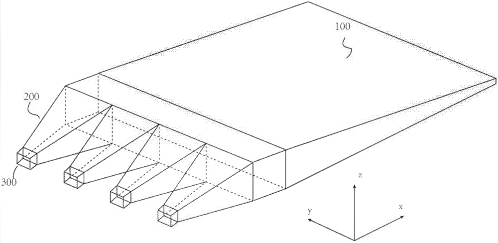
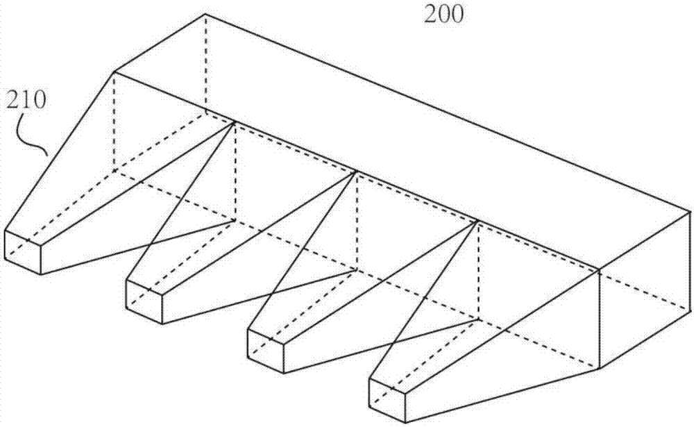
[0028] The collimated backlight structure disclosed by the present invention is as figure 2 As shown, it includes a light guide plate 100 , a light collimating component 200 and an LED light source array 300 . The structure of the light collimation component 200 is as follows: image 3 As shown, an array of light pipes 210 is included. The structure of the light guide is as Figure 4 As shown, it is a square tapered light pipe. The incident surface of the light pipe is 211, the outgoing surface is 212, and the surrounding surface is 213. The light pipe is a solid structure, the material is PMMA, and the surrounding surface of the light pipe is coated with 213 There is a metal reflective layer. As a preferred solution of the present invention, the incident surface and the outgoing surface of the light pipe are square, the side length of the light pipe incident surface is a1, the side length of the outgoing surface is a2, and the length of the light pipe is L, a2 =3*a1, L=1...

Embodiment 2

[0031] The collimated backlight structure disclosed by the present invention is as Figure 10 As shown, it includes a light guide plate 100 , a light collimating component 200 and an LED light source array 300 . The structure of the light collimation component 200 is as follows: Figure 11 As shown, an array of light pipes 210 is included. The structure of the light guide is as Figure 12 As shown, it is a conical light pipe, the incident surface of the light pipe is 211, the exit surface is 212, and the surrounding surface is 213. The light pipe is a hollow core structure, and the material is PMMA. Surface 213 is coated with a metallic reflective layer. As a preferred solution of the present invention, the incident surface and the outgoing surface of the light pipe are circular, the diameter of the light pipe incident surface is a1, the diameter of the outgoing surface is a2, and the length of the light pipe is L, a2= 4*a1, L=20*a1. The LEDs are arranged in one-to-one co...


PUM


Abstract

The invention discloses a collimating backlight structure, a light source array, a light collimating component and a light guide plate. The light source array includes several LED light sources. The light collimating component includes a light pipe array, and the light pipe array is composed of several light pipes, and the light pipes are used for collimating the light emitted by the LED light source. The light guide plate is a flat plate or a wedge-shaped plate structure, and receives the light emitted from the light collimating member. One surface of the light guide plate contains several microstructure units, and several microstructure units have the same structure. The microstructure includes at least two surfaces, one of which is The surface changes the propagation direction of the light in the light guide plate, so that the light is deflected at a certain angle and then exits the light guide plate. The light guide plate does not change the divergence angle of the light emitted by the light collimating component, but only changes the propagation direction of the light emitted by the light collimating component.

Description

technical field [0001] The invention relates to the field of flat panel display technology, in particular to a collimation backlight technology. Background technique [0002] In the field of flat panel display, the backlight source is an important part of the liquid crystal flat panel display, and is used to provide a flat light source for the liquid crystal display. In the prior art, the backlight source is composed of a light source, a light guide plate, a reflection sheet, a diffusion sheet and a prism sheet. Through silk screen printing or engraving a series of uniformly distributed dots, when the light is transmitted to these dots, the condition of total internal reflection is destroyed, the light can be emitted from the light guide plate vertically, and the brightness of the backlight is made uniform through the diffusion sheet, and the prism sheet is used to confine the light To a smaller divergence angle to improve the brightness of the backlight. [0003] The back...

Claims


Application Information

Patent Timeline
Patent Type & Authority Applications(China)
IPC IPC(8): G02B6/00
CPCG02B6/0046G02B6/0055G02B6/0073
Inventor 隆弢
Owner SHANGHAI YUPEI PHOTOELECTRIC TECH CO LTD
Why Eureka
Try Eureka