Optical image system, image capturing device and electronic device

一种光学影像、光轴的技术,应用在光学、光学元件、仪器等方向,达到佳成像品质的效果

Active Publication Date: 2017-11-07
LARGAN PRECISION
View PDF5 Cites 29 Cited by
  • Summary
  • Abstract
  • Description
  • Claims
  • Application Information

AI Technical Summary

Problems solved by technology

The image side surface of the second lens near the optical axis is concave

Method used


Image

  • Optical image system, image capturing device and electronic device
  • Optical image system, image capturing device and electronic device
  • Optical image system, image capturing device and electronic device

Examples


no. 1 example

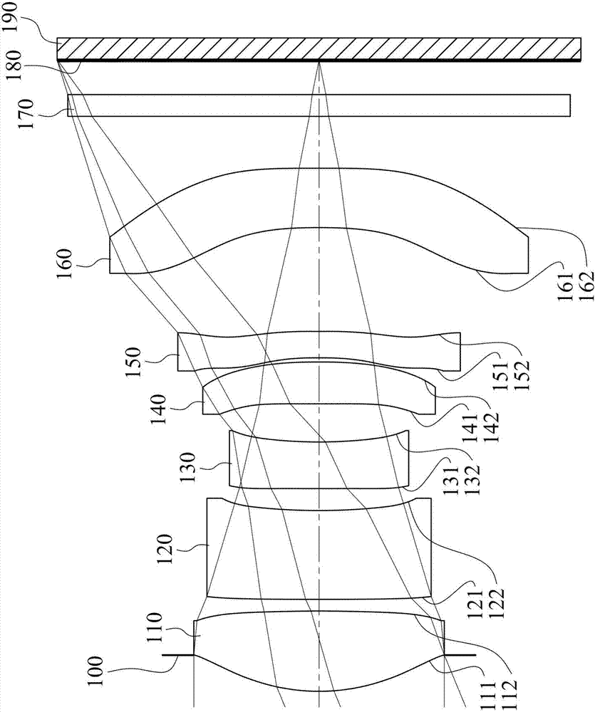
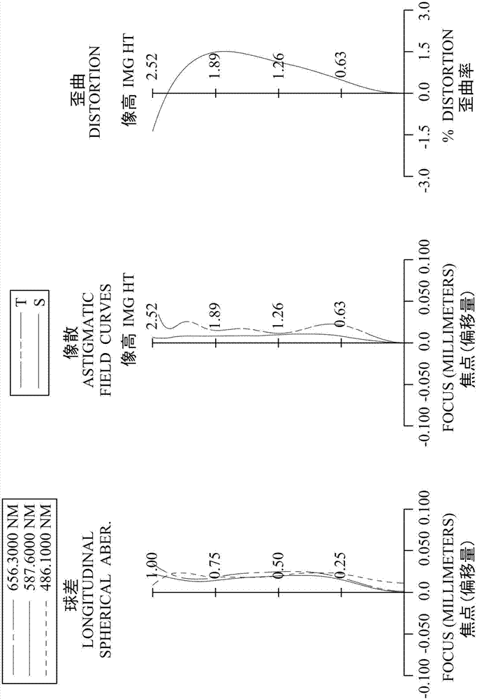
[0128] Please refer to figure 1 and figure 2 ,in figure 1 A schematic diagram showing an imaging device according to the first embodiment of the present invention, figure 2 From left to right are the spherical aberration, astigmatism and distortion curves of the first embodiment. Depend on figure 1 It can be seen that the imaging device of the first embodiment includes an optical imaging system (not labeled separately) and an electronic photosensitive element 190 . The optical imaging system includes an aperture 100, a first lens 110, a second lens 120, a third lens 130, a fourth lens 140, a fifth lens 150, a sixth lens 160, an infrared filter element 170 and imaging surface 180, and the electronic photosensitive element 190 is arranged on the imaging surface 180 of the optical imaging system, wherein the total number of lenses in the optical imaging system is six (110-160), and any two adjacent lenses in the optical imaging system There is an air gap on the optical axi...

no. 2 example

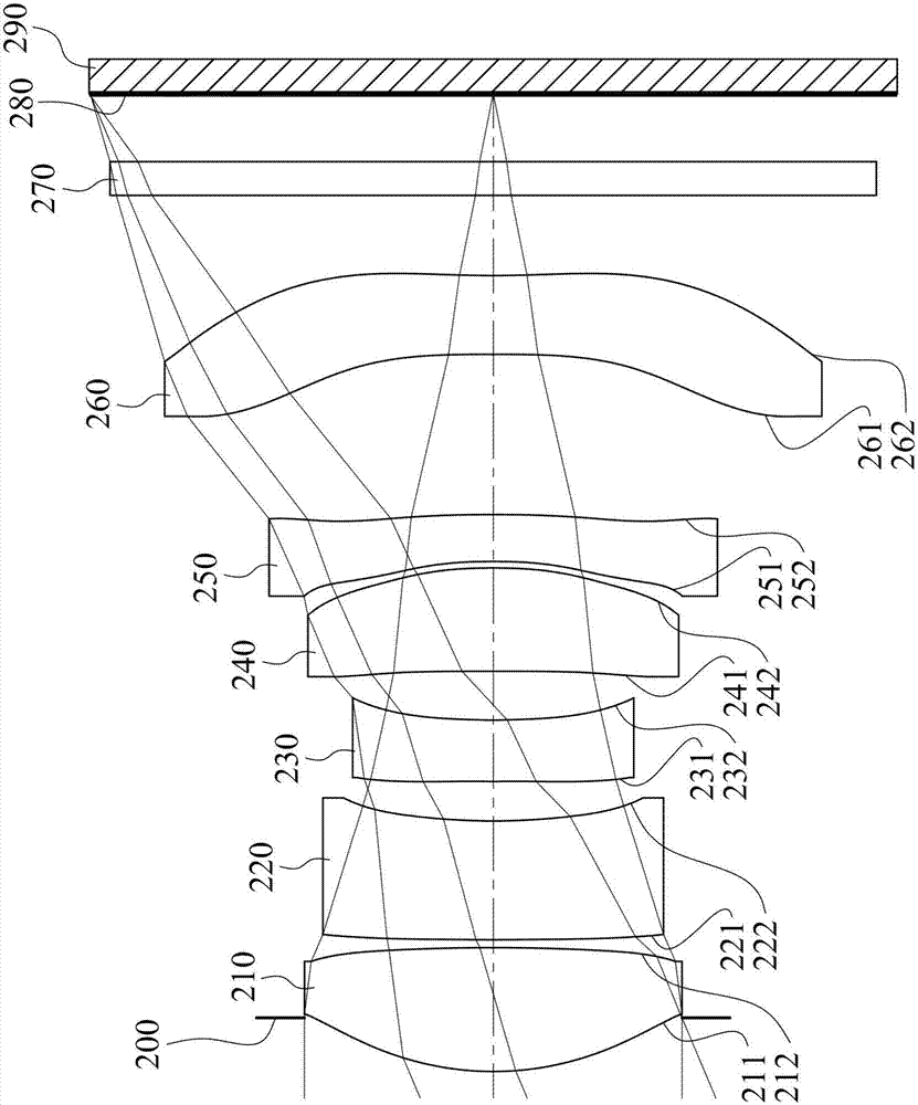
[0163] Please refer to image 3 and Figure 4 ,in image 3 A schematic diagram showing an imaging device according to a second embodiment of the present invention, Figure 4 From left to right are the spherical aberration, astigmatism and distortion curves of the second embodiment. Depend on image 3 It can be seen that the image capturing device of the second embodiment includes an optical imaging system (not otherwise labeled) and an electronic photosensitive element 290 . The optical imaging system includes an aperture 200, a first lens 210, a second lens 220, a third lens 230, a fourth lens 240, a fifth lens 250, a sixth lens 260, an infrared filter element 270 and imaging surface 280, and the electronic photosensitive element 290 is arranged on the imaging surface 280 of the optical imaging system, wherein the total number of lenses in the optical imaging system is six (210-260), and any two adjacent lenses in the optical imaging system There is an air gap on the opt...

no. 3 example

[0182] Please refer to Figure 5 and Figure 6 ,in Figure 5 A schematic diagram showing an imaging device according to a third embodiment of the present invention, Figure 6 From left to right are the spherical aberration, astigmatism and distortion curves of the third embodiment. Depend on Figure 5 It can be seen that the image capturing device of the third embodiment includes an optical imaging system (not labeled separately) and an electronic photosensitive element 390 . The optical imaging system includes a first lens 310, an aperture 300, a second lens 320, a third lens 330, a fourth lens 340, a fifth lens 350, a sixth lens 360, an infrared filter element 370 and imaging surface 380, and the electronic photosensitive element 390 is arranged on the imaging surface 380 of the optical imaging system, wherein the total number of lenses in the optical imaging system is six (310-360), and any two adjacent lenses in the optical imaging system There is an air gap on the op...


PUM


Abstract

The invention discloses an optical image system, an image capturing device and an electronic device. The optical image system includes, in order from an object side to an image side, a first lens element, a second lens element, a third lens element, a fourth lens element, a fifth lens element and a sixth lens element. The first lens element with positive refractive power has an object-side surface being convex in a paraxial region thereof. The second lens element has an image-side surface being concave in a paraxial region thereof. The third lens element has negative refractive power. The fifth lens element with negative refractive power has an object-side surface and an image-side surface being both aspheric. The sixth lens element has an object-side surface and an image-side surface being both aspheric.

Description

technical field [0001] The present invention relates to an optical image system and an image capturing device, and in particular to a miniaturized optical image system and an image capturing device applied to an electronic device. Background technique [0002] As the application of camera modules becomes more and more extensive, it will be a major trend of future technological development to install camera modules in various smart electronic products, vehicle devices, identification systems, entertainment devices, sports devices and home intelligent assistance systems. In order to have a wider application field, smart devices equipped with one, two, or even more than three lenses have gradually become the mainstream of the market, and in response to different application requirements, lens systems with different characteristics have been developed. [0003] Moreover, in recent years, electronic products have demanded thinner and lighter, so traditional photographic lenses, e...

Claims


Application Information

Patent Timeline
Patent Type & Authority Applications(China)
IPC IPC(8): G02B13/00G02B13/18
CPCG02B13/0045G02B13/18G02B9/62G02B27/0025
Inventor 廖凌峣薛钧哲吴建勳陈纬彧
Owner LARGAN PRECISION
Why Eureka
Try Eureka