
Touch electrode array and touch display device

A technology of touch electrodes and arrays, which is applied in the fields of touch electrode arrays and touch display devices, can solve the problems of touch panel yield and reliability decline, and achieve the effect of improving yield and reliability and reducing probability

Inactive Publication Date: 2017-11-07
AU OPTRONICS CORP
View PDF9 Cites 5 Cited by
  • Summary
  • Abstract
  • Description
  • Claims
  • Application Information

AI Technical Summary

Problems solved by technology

The bridge part damaged by static electricity causes the yield and reliability of the touch panel to drop

Method used


Image

  • Touch electrode array and touch display device
  • Touch electrode array and touch display device
  • Touch electrode array and touch display device

Examples


Embodiment Construction

[0070] Below in conjunction with accompanying drawing, structural principle and working principle of the present invention are specifically described:

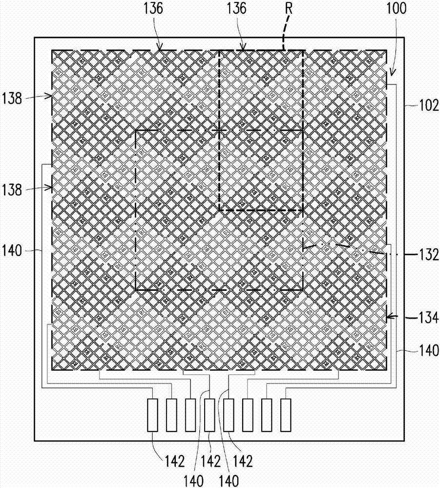
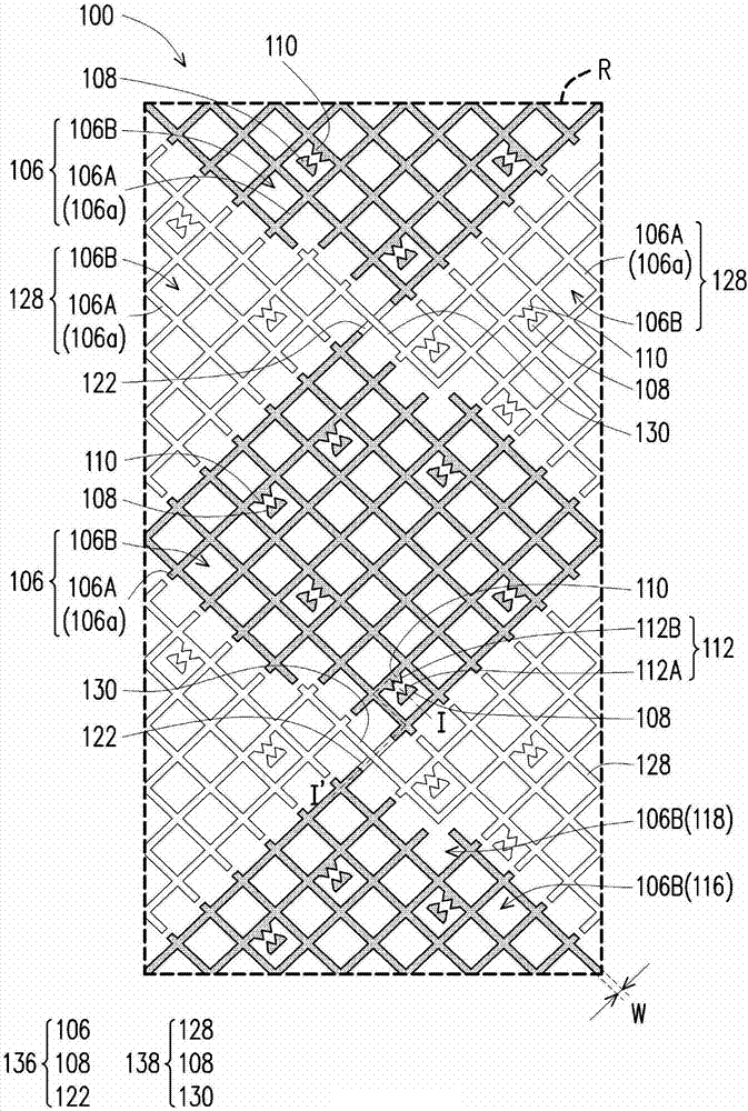
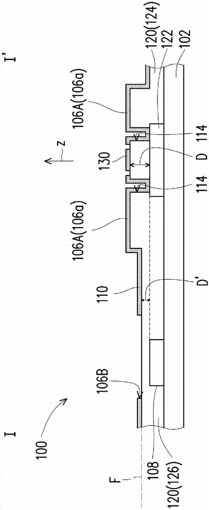
[0071] figure 1 is a schematic top view of a touch electrode array according to an embodiment of the present invention. figure 2 yes figure 1 The enlarged schematic diagram of the local R of the touch electrode array. image 3 is based on figure 2 The schematic cross-sectional view of the touch electrode array drawn by the section line I-I'.

[0072] Please refer to figure 1 , the touch electrode array 100 is disposed on the substrate 102 . The substrate 102 has a central region 132 and an edge region 134 substantially surrounding the central region 132 . figure 1 The middle area 132 and the edge area 134 are exemplarily marked, but the present invention is not limited thereto, and the ranges of the middle area 132 and the edge area 134 may vary depending on actual applications. In this embodiment, the material of the...


PUM


Abstract

A touch electrode array and a touch display device are disclosed. The touch electrode array is disposed on a substrate and includes at least one first sensing electrode and at least one guard electrode. The first sensing electrode is made of a mesh structure. The mesh structure includes a solid portion and at least one open portion defined by the solid portion. The at least one guard electrode overlaps the at least one open portion in one direction. additionally the touch display device comprising the touch electrode array is put forward.

Description

technical field [0001] The present invention relates to an electrode array and an electronic device including the electrode array, and in particular to a touch electrode array and a touch display device. Background technique [0002] In recent years, a touch panel has become one of the popular electronic devices in daily life. Electronic devices usually include many signal wires to transmit signals. However, these signal wires may become discharge paths for electrostatic discharge, especially the thinner signal wires are more likely to be damaged by the large current generated during electrostatic discharge, resulting in damage to the signal wires. Taking the touch panel as an example, the areas that are most likely to be damaged by static electricity concentrate on the bridges of the sensing electrodes. The bridge portion damaged by static electricity reduces the yield and reliability of the touch panel. In view of this, how to design a touch panel with an electrostatic ...

Claims


Application Information

Patent Timeline
Patent Type & Authority Applications(China)
IPC IPC(8): G06F3/044G06F3/041
CPCG06F3/0416G06F3/044G06F2203/04112G06F2203/04103G06F2203/04111G06F3/0443G06F3/0446G06F3/041
Inventor 朱育进郑胜文
Owner AU OPTRONICS CORP
Learn More