Non-polarity high voltage DC contactor arc extinguishing system structure

A high-voltage direct current, system structure technology, applied in the direction of relays, electromagnetic relays, detailed information of electromagnetic relays, etc., can solve the problems of low life of on-load switching, large contactor size, waste of installation space, etc., and achieve good arc extinguishing effect and shrink Small size, saving installation space

Inactive Publication Date: 2017-11-07
昆山国力源通新能源科技有限公司
View PDF4 Cites 6 Cited by
  • Summary
  • Abstract
  • Description
  • Claims
  • Application Information

AI Technical Summary

Problems solved by technology

The arc extinguishing of existing DC contactors mainly depends on increasing the gap and pressure of the contacts to improve the arc extinguishing ability, but the arc extinguishing effect of the above arc extinguishing method will be relatively poor under high voltage and high power load conditions, resulting in Low switching life
Moreover, the above-mentioned arc extinguishing method will also cause the contactor to be bulky and waste installation space.

Method used


Image

  • Non-polarity high voltage DC contactor arc extinguishing system structure
  • Non-polarity high voltage DC contactor arc extinguishing system structure
  • Non-polarity high voltage DC contactor arc extinguishing system structure

Examples


Embodiment 1

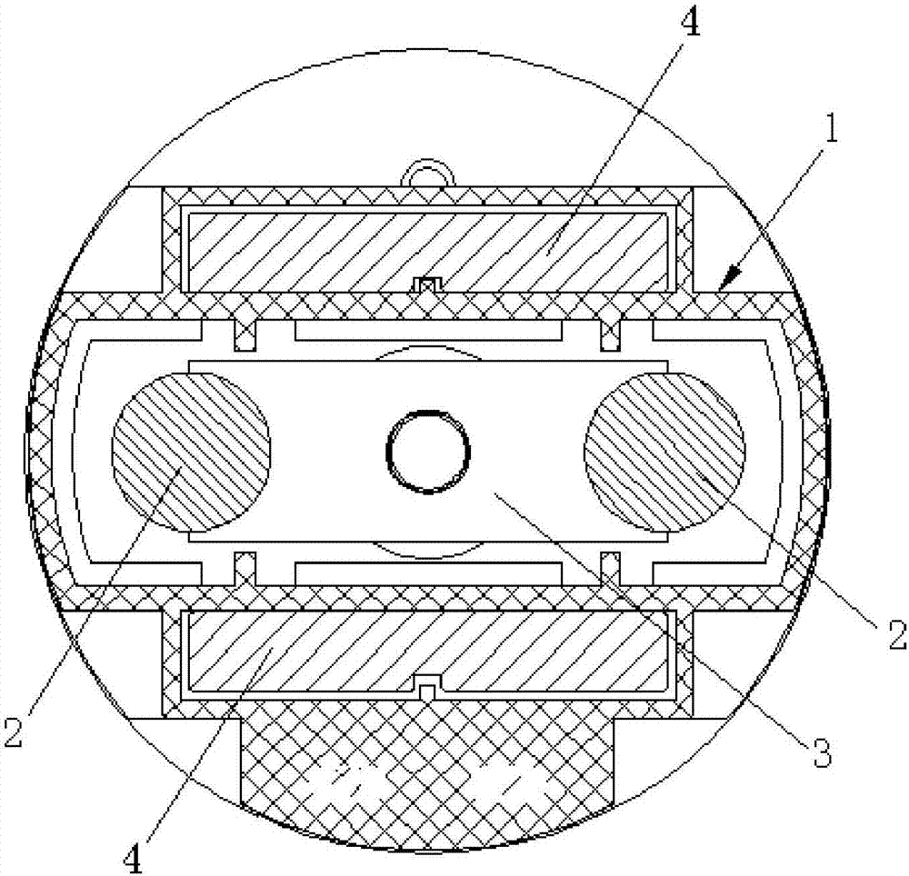
[0021] Please refer to the attached figure 1 As shown, it shows a schematic cross-sectional structure diagram of the first embodiment of the arc extinguishing system structure of the non-polar high-voltage DC contactor of the present invention. The arc extinguishing system structure of the non-polar high-voltage DC contactor includes an arc extinguishing chamber 1, two static contact points 2 arranged side by side on the top of the arc extinguishing chamber 1, and a movable built-in arc extinguishing chamber 1 The moving contact piece 3, the moving contact piece 3 and the two static contact points 2 are vertically opposite to each other, and the moving contact piece 3 can also communicate with the two static contact points 2, or the The moving contact piece 3 can also be disconnected from the two static contact points 2 respectively (it is common knowledge and does not belong to the focus of the present invention, so it will not be described in detail here); particularly, at t...

Embodiment 2

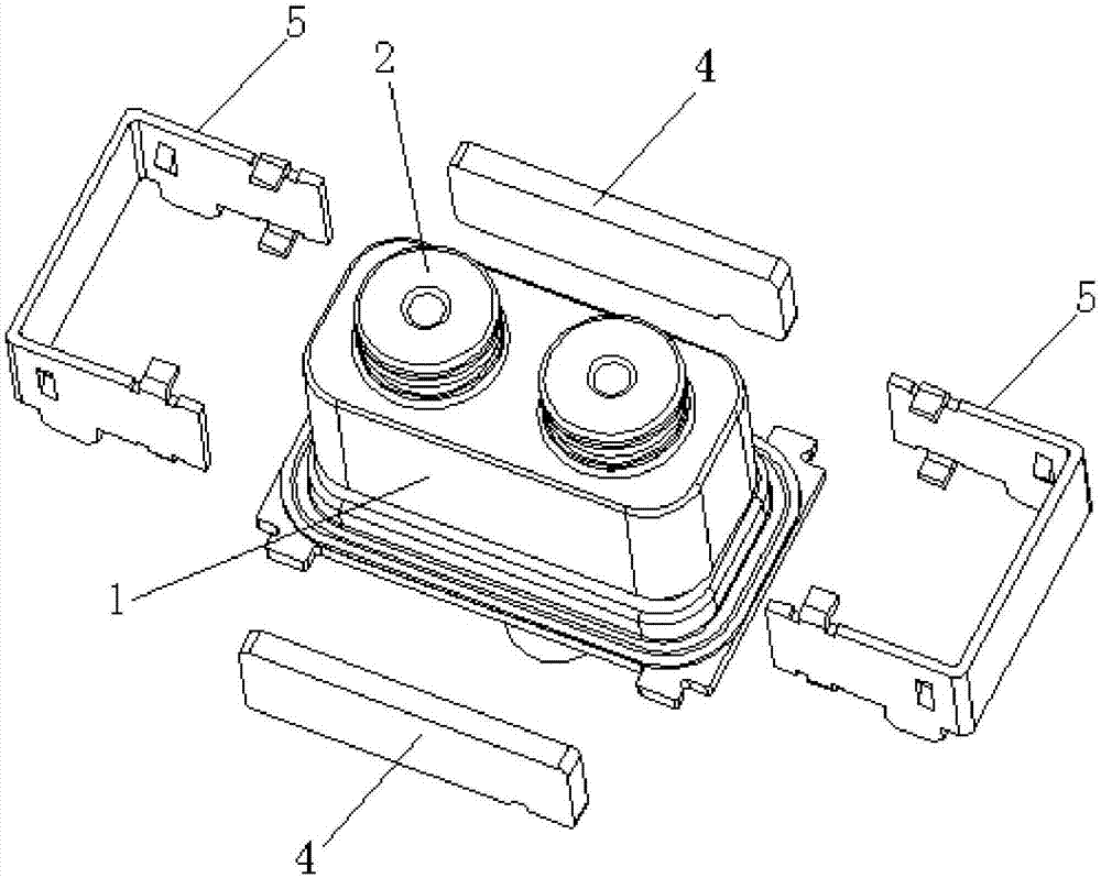
[0024] Please refer to the attached figure 2 , which shows a schematic diagram of the exploded structure of the second embodiment of the arc extinguishing system structure of the non-polar high-voltage DC contactor of the present invention. The structure of the non-polar high-voltage DC contactor arc extinguishing system shown in Embodiment 2 is generally similar to the structure of the non-polar high-voltage DC contactor arc extinguishing system shown in Embodiment 1. The main difference is that in Embodiment 1, the two The permanent magnets 4 are all built in the arc extinguishing chamber 1; and in embodiment 2, the two permanent magnets 4 are relatively arranged on the outer surface of the side wall of the arc extinguishing chamber 1 through two brackets 5 .

[0025] In addition, in embodiment 2, it is further preferred that the arc extinguishing chamber 1 is formed by sintering and sealing ceramics and metal; the upper end surface of each permanent magnet 4 is higher tha...


PUM


Abstract

The invention discloses a non-polarity high voltage DC contactor arc extinguishing system structure comprising a spark chamber, two static contact points arranged in parallel on the spark chamber top, and a movable contact sheet movably built in the spark chamber; the movable contact sheet and the two static contact points are respectively vertically arranged in opposite; the movable contact sheet is respectively connected with the two static contact points, or the movable contact sheet is respectively disconnected from the two static contact points; two opposite sides of the static contact points are respectively provided with a permanent magnet; the connecting line direction between the two permanent magnets and that between the two static contact points are mutually vertical to each other; the two permanent magnets are same in polarities; by using said structure innovations, the arc extinguishing system structure enables the arcs formed between the movable contact sheet and the two static contact points to have the same diffusion directions, and a parallel state can be always kept, thus effectively preventing the arcs formed between the movable contact sheet and the two static contact points from making contacts, and causing short circuits; the non-polarity high voltage DC contactor arc extinguishing system structure can realize non-polarity arc extinguishing.

Description

technical field [0001] The invention relates to the technical field of DC contactors, and specifically provides an arc extinguishing system structure for a non-polar high-voltage DC contactor. Background technique [0002] As we all know, in order to improve the on-load switching capability of high-voltage DC contactors, it is necessary to solve the arc-extinguishing capability of its contact system. The arc extinguishing of existing DC contactors mainly depends on increasing the gap and pressure of the contacts to improve the arc extinguishing ability, but the arc extinguishing effect of the above arc extinguishing method will be relatively poor under high voltage and high power load conditions, resulting in Switching life is low. Moreover, the above-mentioned arc extinguishing method will also result in a large volume of the contactor, which wastes installation space. [0003] In view of this, the present invention is proposed. Contents of the invention [0004] In or...

Claims


Application Information

Patent Timeline
Patent Type & Authority Applications(China)
IPC IPC(8): H01H50/38H01H9/44
CPCH01H50/38H01H9/443
Inventor 董洪江周伟钢顾春朋吴芳潘乔旭
Owner 昆山国力源通新能源科技有限公司
Why Eureka
Try Eureka