Motor direct-drive reel needle winding mechanism

A winding mechanism and needle winding technology, which is applied in battery assembly machines, secondary battery manufacturing, non-aqueous electrolyte batteries, etc., can solve the problems of transmission response time lag, transmission structure rigidity and transmission accuracy, etc., and improve transmission accuracy. , The effect of simplifying the rigidity of the transmission structure and transmission accuracy, and the compact structure

Pending Publication Date: 2017-11-07
SHENZHEN GEESUN INTELLIGENT TECHNOLOGY CO LTD
View PDF7 Cites 2 Cited by
  • Summary
  • Abstract
  • Description
  • Claims
  • Application Information

AI Technical Summary

Problems solved by technology

[0003] The purpose of this application is to address the above problems and propose a motor direct-driven needle winding mechanism with a simple and compact structure to solve the problem of low transmission structure rigidity and transmission precision caused by the multi-stage transmission of the existing needle winding mechanism. Drive response time lag problem

Method used


Image

  • Motor direct-drive reel needle winding mechanism
  • Motor direct-drive reel needle winding mechanism
  • Motor direct-drive reel needle winding mechanism

Examples


Embodiment 1

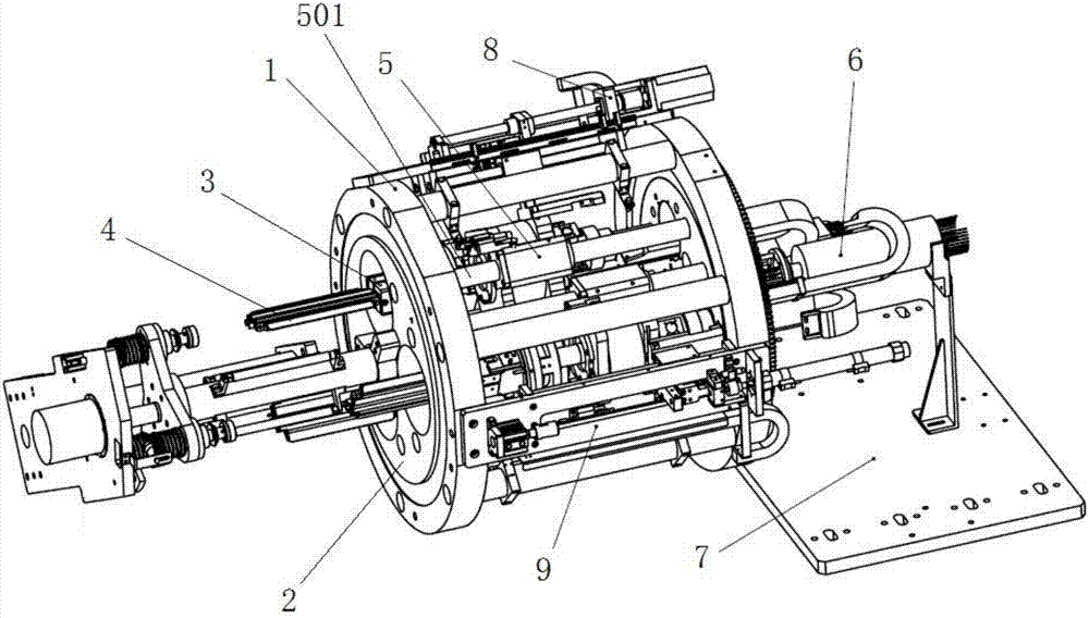
[0047] Figure 1 to Figure 3 It shows a specific embodiment of the motor direct-driven needle winding mechanism of the present application, which is the same as the traditional needle winding mechanism, and it also includes: an outer support frame 1, which is rotatably arranged on the outer support frame Turntable 2, rolling needle mounting seat 3, rolling needle 4 installed on the rolling needle mounting seat.

[0048] The key improvement of this embodiment is that the needle winding mechanism also includes a direct drive motor 5 connected to the turntable 2, the motor shaft 501 of the direct drive motor 5 is directly connected with the needle mounting base 3, and the direct drive motor 5 can move axially forward and backward relative to the turntable 2 (the direct drive motor 5 is connected with the turntable 2 through a sliding connection). When working, the direct-drive motor 5 is energized to run, and the motor shaft 501 rotates, thereby driving the rolling needle mounti...

Embodiment 2

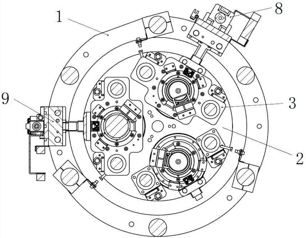
[0062] Figure 4 and Figure 5 It shows the second specific embodiment of the motor direct-driven needle winding mechanism of the present application. Its structure is similar to that of Embodiment 1, and also includes the outer support frame 1, which rotates the turntable 2 arranged on the outer support frame, and rotates The rolling needle mounting seat 3 arranged on the turntable, the rolling needle 4 arranged on the rolling needle mounting seat, the pin insertion assembly (not shown in the figure) and the setting needle assembly (not shown in the figure) installed on the outer support frame , fixed on the direct drive motor 5 on the turntable 2. The motor shaft 501 of the direct drive motor 5 is directly connected with the needle rolling seat 3 .

[0063] The main difference between this embodiment and the above-mentioned first embodiment is that there are only two winding needles 4 in this embodiment, and correspondingly, there are two winding needle mounting bases 3 an...

Embodiment 3

[0066] Figure 6 and Figure 7 It shows the third specific embodiment of the motor direct-driven needle winding mechanism of the present application. Its structure is similar to that of Embodiment 1, and also includes the outer support frame 1, which rotates the turntable 2 arranged on the outer support frame, and rotates The rolling needle mounting seat 3 arranged on the turntable, the rolling needle 4 arranged on the rolling needle mounting seat, the pin insertion assembly (not shown in the figure) and the setting needle assembly (not shown in the figure) installed on the outer support frame , fixed on the direct drive motor 5 on the turntable 2. The motor shaft 501 of the direct drive motor 5 is directly connected with the needle rolling seat 3 .

[0067] The main difference between this embodiment and the above-mentioned first embodiment is that only one winding needle 4 is provided in this embodiment, and correspondingly, only one winding needle mounting base 3 and dire...


PUM


Abstract

The application discloses a motor direct-drive reel needle winding mechanism, comprising an outer support frame, a swivel plate rotatably arranged on the outer support frame, a reel needle mounting seat, a reel needle installed on the reel needle mounting seat, and a direct drive motor connected with the swivel plate in a way of axial movement, wherein a motor shaft of the direct drive motor is directly connected with the reel needle mounting seat so as to drive the reel needle installed on the reel needle mounting seat to make rotational motion. The motor direct-drive reel needle winding mechanism solves the problems that the existing reel needle winding mechanism adopts multistage transmission, so that a transmission structure is low in rigidity, the transmission accuracy is low, transmission response time is delayed, and the like.

Description

technical field [0001] The present application relates to the field of lithium battery production equipment, in particular to a winding mechanism directly driven by a motor. Background technique [0002] The existing needle winding mechanism mostly adopts the hollow shaft, synchronous pulley and synchronous belt connection and transmission mode to realize winding, which is a two-stage or above transmission mode. This method requires high precision of parts processing and assembly. There are many parts used, and the assembly is more complicated; the winding needle transmission is different, and the reliability is low; the overall moment of inertia is large, the acceleration and deceleration are slow, the winding efficiency is low, the cost is expensive, and the required winding accuracy is often not achieved. Contents of the invention [0003] The purpose of this application is to address the above problems and propose a motor direct-driven needle winding mechanism with a s...

Claims


Application Information

Patent Timeline
Patent Type & Authority Applications(China)
IPC IPC(8): H01M10/058
CPCH01M10/0404H01M10/058Y02E60/10Y02P70/50
Inventor 陈飞王建东阳如坤
Owner SHENZHEN GEESUN INTELLIGENT TECHNOLOGY CO LTD
Why Eureka
Try Eureka