Dynamic mixer and method for mixing components

A technology of dynamic mixers and mixers, applied in fluid mixers, chemical instruments and methods, shaking/oscillating/vibrating mixers, etc.

Active Publication Date: 2017-11-10
MARCO SYSTEMANALYSE UND ENTWICKLUNG GMBH
View PDF5 Cites 0 Cited by
  • Summary
  • Abstract
  • Description
  • Claims
  • Application Information

AI Technical Summary

Problems solved by technology

[0002] The known dynamic mixer has the disadvantage that the rotor separates the space in the mixing chamber, so that there is a volume swept by the rotor and a volume not swept by the rotor in the mixing chamber

Method used


Image

  • Dynamic mixer and method for mixing components
  • Dynamic mixer and method for mixing components
  • Dynamic mixer and method for mixing components

Examples


Embodiment Construction

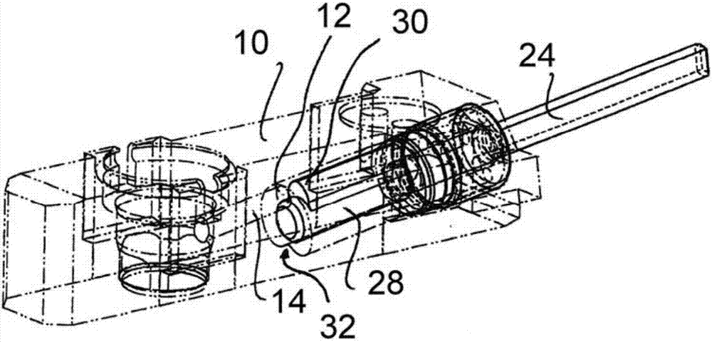
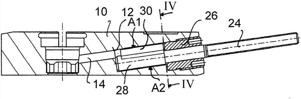
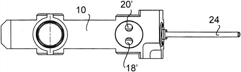
[0024] figure 1 Shown is a housing 10 of a metering valve, which is not shown in more detail and is integrated into a dynamic mixer whose outlet 12 communicates via a media channel 14 with a metering valve (not shown). Therefore, the housing 10 of the metering valve also constitutes the housing of the dynamic mixer, in which a mixing chamber 16 is arranged, the cross section of the mixing chamber 16 can be in Figure 4 and Figure 5 easily identifiable in. The mixing chamber 16 has a first inlet 18 and a second inlet 20 , into which a first inlet channel 18 ′ and a second inlet channel 20 ′ open to supply the two fluid components of the medium to be mixed. It should be understood that more than two inlets or more than one outlet may also be provided.

[0025] A mixing element 22 is arranged in the mixing chamber 16 for thoroughly mixing the components to be mixed in a small volume and in a short time, wherein the mixing element 22 can be rotated in the mixing chamber via a ...


PUM


Abstract

A dynamic mixer and a method for mixing two components. A dynamic mixer comprises a mixing chamber having a plurality of inlets and an outlet as well as a mixing element rotatably arranged in the mixing chamber. The mixing takes place by a to and fro movement of the mixing element.

Description

technical field [0001] The present invention relates to a device and method for mixing components, and in particular to a dynamic mixer having a mixing chamber with at least a first and a second inlet and an outlet, wherein the mixing elements can Arranged rotationally within the mixing chamber. Background technique [0002] Known dynamic mixers of this type have the disadvantage that the rotor separates the space in the mixing chamber, so that there is a volume swept by the rotor and a volume not swept by the rotor within the mixing chamber. Consequently, sections are formed in the region of the rotor and in the regions of the mixing chamber that do not flow sufficiently, ie the medium containing the components to be mixed either moves too slowly at the walls of the mixing chamber due to braking , or the medium is also rotated by the rotor—especially also in the vicinity of the rotor's axis—so that the medium has a very low relative velocity to the rotor and to the rotor's...

Claims


Application Information

Patent Timeline
Patent Type & Authority Applications(China)
IPC IPC(8): B01F5/00B01F5/06
CPCB01F25/00B01F25/438B01F2215/0422B01F2215/0431B01F31/445B01F35/53B01F27/09B01F27/11B01F35/71B01F35/75B01F35/71805
Inventor 马丁·路透
Owner MARCO SYSTEMANALYSE UND ENTWICKLUNG GMBH
Why Eureka
Try Eureka