Punching equipment

A technology of stamping equipment and stamping dies, applied in metal processing equipment, metal processing, piercing tools, etc., can solve the problems of reducing punching efficiency, single stamping structure, complex structure, etc., to improve work efficiency and quality, and simplify stamping equipment , stamping accurate effect

Inactive Publication Date: 2017-11-10
JIASHAN RUIYI ELECTRONICS TECH
View PDF6 Cites 3 Cited by
  • Summary
  • Abstract
  • Description
  • Claims
  • Application Information

AI Technical Summary

Problems solved by technology

[0002] Stamping is to rely on presses and molds to apply external force to plates, strips, pipes and profiles, etc., to cause plastic deformation or separation, so as to obtain workpieces (stamping parts) of required shape and size. Stamping can be used on steel plates , leather, cloth, wood and other materials, the existing stamping equipment is fixed on the template with a punch suitable for the groove on the stamping die, and the template is connected with the cylinder that drives it to move up and down. Driven by the drive, the template drives the punch to move up and down relative to the groove, so as to punch out the required graphics on the workpiece that is processed between the punch and the groove. Moving down will neither rotate nor remove the burrs on the surface of the workpiece after stamping. The structure is single, so it is necessary to design a punching device with high punching quality and can punch a variety of shapes

Method used


Image

  • Punching equipment
  • Punching equipment
  • Punching equipment

Examples


Embodiment Construction

[0022] In order to make the technical means, creative features, goals and effects achieved by the present invention easy to understand, the present invention will be further elaborated below in conjunction with illustrations and specific embodiments.

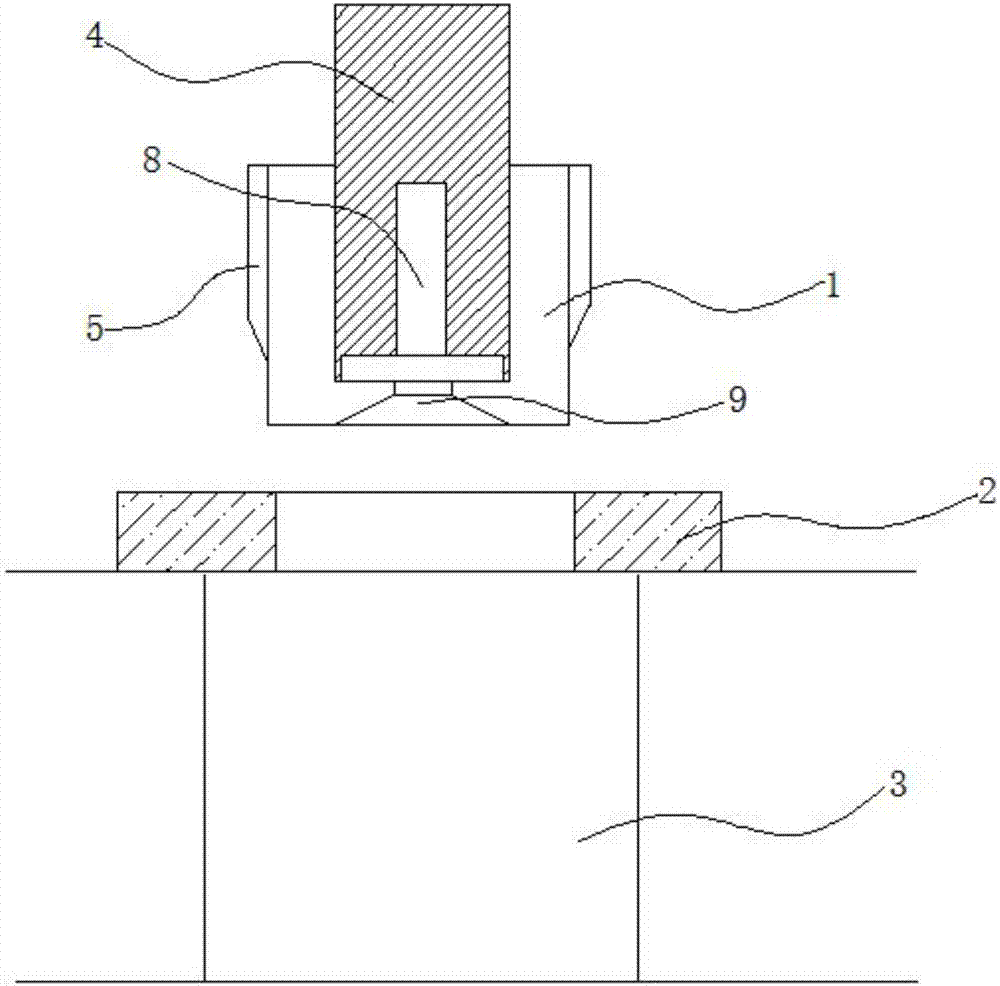
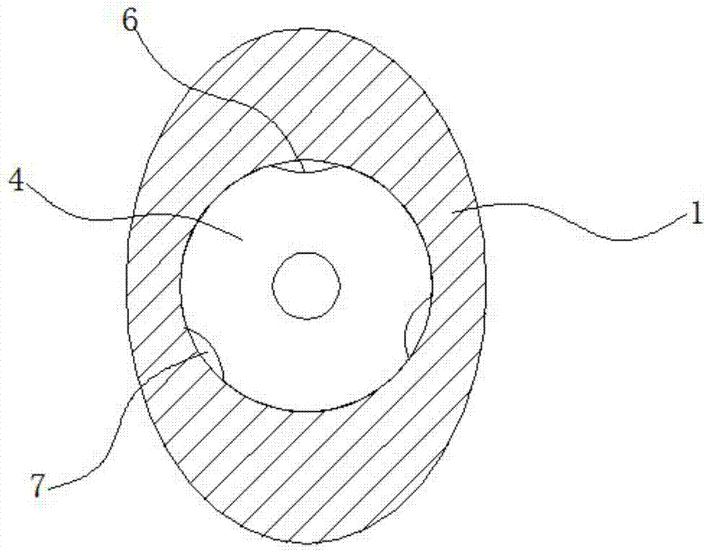
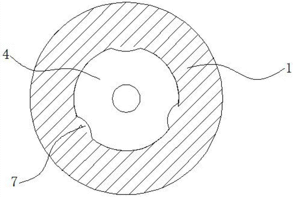
[0023] refer to figure 1 , figure 2 , image 3 , Figure 4 As shown, this kind of stamping equipment includes a punch 1, a stamping die 2 and a support seat 3, the stamping die 2 is installed on the support seat 3, the punch 1 is located above the support seat 3, and the center of the stamping die 2 is provided with a concave groove, the punch 1 can be pressed into the groove in the middle of the stamping die 2, the central section of the punch 1 is circular, the punch 1 is nested at the bottom end of the main shaft 4, and the outer wall of the punch 1 is provided with a Grinding sleeve 5, the wear-resistant sleeve 5 is installed on the middle and upper end of the punch 1;

[0024] The lower end of the punch 1 is provided w...


PUM


Abstract

A stamping equipment, including a punch, a stamping die and a support seat, the stamping die is installed on the support seat, the punch is located above the support seat, a groove is arranged in the center of the stamping die, and the punch can be pressed into the middle of the stamping die In the groove of the punch, the central section of the punch is circular, the punch is nested at the bottom end of the main shaft, and the outer wall of the punch is provided with a wear-resistant sleeve, which is installed at the middle and upper end of the punch; The equipment makes its structure simple, and can punch round holes and non-round holes, and can process a variety of materials with accurate punching. After punching, the punch can rotate under the action of the main shaft, and the wear-resistant sleeve on the punch can be removed by rotation. The burr on the edge of the punching part of the stamped workpiece improves work efficiency and quality.

Description

technical field [0001] The invention relates to the technical field of stamping, in particular to stamping equipment. Background technique [0002] Stamping is to rely on presses and molds to apply external force to plates, strips, pipes and profiles, etc., to cause plastic deformation or separation, so as to obtain workpieces (stamping parts) of required shape and size. Stamping can be used on steel plates , leather, cloth, wood and other materials, the existing stamping equipment is fixed on the template with a punch suitable for the groove on the stamping die, and the template is connected with the cylinder that drives it to move up and down. Driven by the drive, the template drives the punch to move up and down relative to the groove, so as to punch out the required graphics on the workpiece that is processed between the punch and the groove. However, the commonly used stamping equipment is only used by the piston rod of the cylinder Moving down will neither rotate nor ...

Claims


Application Information

Patent Timeline
Patent Type & Authority Applications(China)
IPC IPC(8): B21D28/34B26F1/14
CPCB21D28/34B21D28/246B26F1/14
Inventor 钱明奎
Owner JIASHAN RUIYI ELECTRONICS TECH
Why Eureka
Try Eureka