Rebar arc bending machine

A technology of bending arcs and steel bars, which is applied in the field of steel bar processing, which can solve the problems of affecting the processing accuracy of steel bars, easy lifting of steel bars, and long time, so as to achieve good processing effects, reduce manpower, and increase floor space.

Active Publication Date: 2017-11-10
XUZHOU MASTER MECHANICAL TECH CO LTD
View PDF9 Cites 3 Cited by
  • Summary
  • Abstract
  • Description
  • Claims
  • Application Information

AI Technical Summary

Problems solved by technology

The steel bar bending machine is a machine that bends steel bars into a certain arc. It is one of the indispensable equipment for steel bar processing. It is mainly used for bending steel bars in engineering construction. The steel bar bending machine in the prior art mainly includes the frame , the frame is provided with an active pressure roller and a driven pressure roller, the active pressure roller is connected to the power device, and the active pressure roller is reversed during work so as to drive the steel bar to move left and right, so that the steel bar can be gradually pressed into an arc shape or Circle, because a part of the steel bar in the form of a circle is vacant, in order to ensure the bending effect, workers need to hold the vacant part with their hands, and the end of the steel bar is easy to warp during the bending process, which has certain dangers. Some dynamic pressure rollers are adjustable and some are non-adjustable. Adjusting the distance of the driven pressure roller can change the bending arc of the steel bar, and the processing range is wide. In the prior art, the number of driven pressure rollers is generally two, and the two One separate adjustment, this adjustment method is not easy to control the adjustment distance of the two driven pressure rollers is exactly the same, it is easy to produce errors and affect the processing accuracy of the steel bar, and the two separate adjustments take a long time

Method used


Image

  • Rebar arc bending machine
  • Rebar arc bending machine

Examples


Embodiment Construction

[0011] The present invention will be described in further detail below in conjunction with the accompanying drawings.

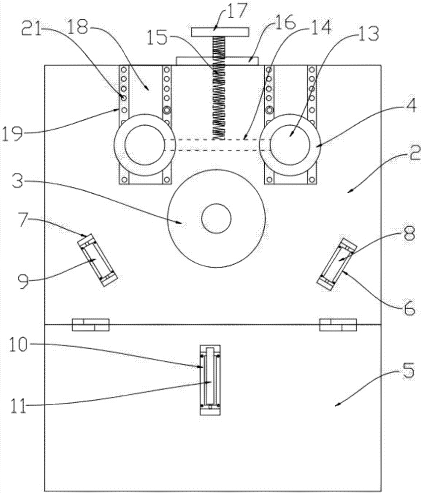
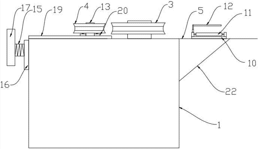
[0012] In conjunction with the accompanying drawings, a steel bar arc bending machine includes a body 1, a power device is provided inside the body 1, a working table 2 is provided on the body 1, and a power device is provided on the working table 2. The connected driving pressure roller 3 and the two driven pressure rollers 4 that cooperate with the driving pressure roller 2 are characterized in that: the body 1 is hinged with a folding plate 5 on the side close to the driving pressure roller 3, and the Utilize bolt connection to be provided with pedestal one 6 and pedestal two 7 on the working surface 2 of the above, described pedestal one 6, pedestal two 7 are provided with the cylinder one 8, cylinder two 9 that are used to support steel bar, described Folding plate 5 is provided with seat three 10, and described seat three 10 is provided with roller thre...


PUM


Abstract

The invention discloses a rebar arc bending machine. The rebar arc bending machine comprises a machine body (1), a workbench face (2), a driving pressing roller (3), driven pressing roller (4) and rotating shafts (13), and is characterized in that the side, close to the driving pressing roller (3), on the machine body (1) provided with a folding plate (5) in a hinged manner; a base body is arranged on the workbench face (2), and is provided with a roller; a connection rod (14) is arranged between two rotating shafts (13), and is provided with a screw rod (15); the workbench face (2) is provided with a sliding groove (19) with an opening; and the rotating shafts (13) can move on the sliding groove (19). According to the rebar arc bending machine, the two driven pressing rollers can be adjusted at the same time through a handle, precision is high, adjusting is convenient, the workbench face can be increased due to a hinged supporting plate, the machining effect is good when a rebar is placed on the roller, it is not needed to hold the rebar by human hands, manpower is reduced, the supporting plate is laid down when the rebar arc bending machine is not used, and the floor space cannot be increased.

Description

technical field [0001] The invention relates to the technical field of steel bar processing, in particular to a steel bar arc bending machine. Background technique [0002] With the development of science and technology and the improvement of people's living standards, the infrastructure of the country is becoming more and more perfect, and high-rise buildings are rising everywhere. Reinforced concrete is widely used in construction, and it is often necessary to bend steel bars into various shapes, especially in prefabricated concrete. During the construction of pipes, tunnels, etc. The steel bar bending machine is a machine that bends steel bars into a certain arc. It is one of the indispensable equipment for steel bar processing. It is mainly used for bending steel bars in engineering construction. The steel bar bending machine in the prior art mainly includes the frame , the frame is provided with an active pressure roller and a driven pressure roller, the active pressur...

Claims


Application Information

Patent Timeline
Patent Type & Authority Applications(China)
IPC IPC(8): B21F1/00
CPCB21F1/004
Inventor 郭楠楠
Owner XUZHOU MASTER MECHANICAL TECH CO LTD
Why Eureka
Try Eureka