Arm type laser machine

A laser machine and arm technology, applied in laser welding equipment, welding equipment, metal processing equipment, etc., can solve the problems of cumbersome structure, huge volume, high load requirements of mobile modules, etc. Effect

Active Publication Date: 2017-11-10
深圳市新迪精密科技有限公司
View PDF7 Cites 0 Cited by
  • Summary
  • Abstract
  • Description
  • Claims
  • Application Information

AI Technical Summary

Problems solved by technology

This method is that the optical path is wrapped in the entire module, there is no hidden danger of light leakage, and the position of the optical path is easy to control; the disadvantage is that it is bulky, heavy in structure, and has high requirements on the load of the mobile module, which is not convenient for high-speed movement

Method used


Image

  • Arm type laser machine
  • Arm type laser machine
  • Arm type laser machine

Examples


Embodiment Construction

[0022] The present invention will be further described in detail below through specific embodiments in conjunction with the accompanying drawings.

[0023] In this embodiment, an arm-type laser machine is provided, and the arm-type structure can also be used in other devices with optical paths.

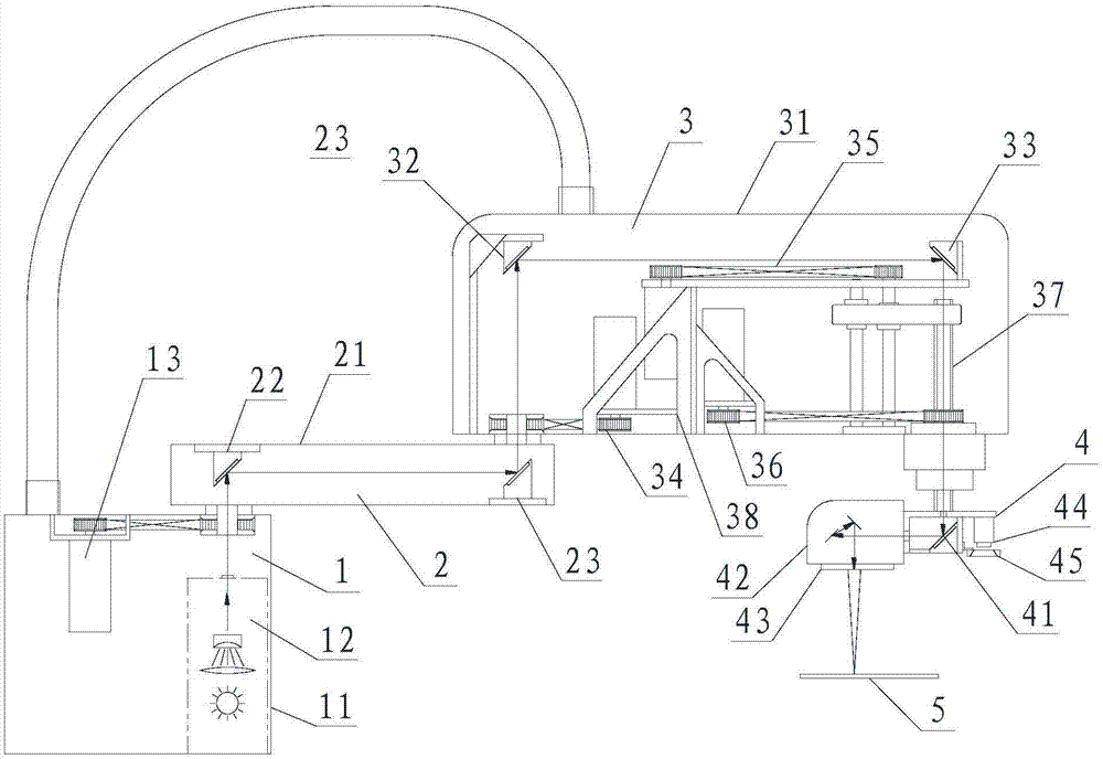
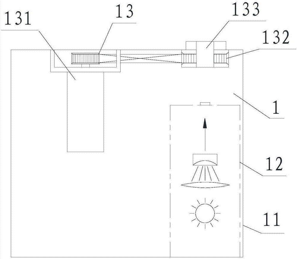
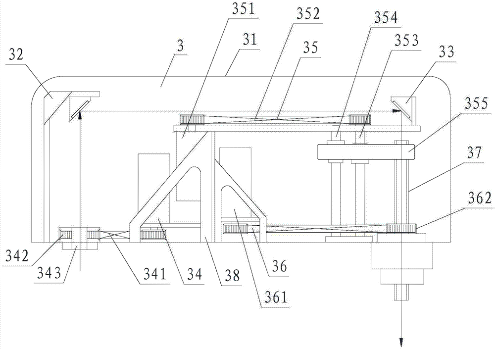
[0024] Such as figure 1 As shown, the arm-type laser machine of this embodiment includes an A-axis base assembly 1, a B-axis base assembly 2, a C-axis base assembly 3 and a lens module 4 (ie, a working head), and the A-axis base assembly 1 is fixed In the preset position, the B-axis base assembly 2 is installed on the A-axis base assembly 1 for rotation along the A-axis, and the C-axis base assembly 3 is installed on the B-axis base assembly 2 for rotation along the B-axis The lens module 4 is mounted on the C-axis base assembly 3 for rotation and axial movement along the C axis, so that the lens module 4 can move along the X, Y, and Z axes and rotate along the Z axis. A flexible pi...


PUM


Abstract

The invention discloses an arm type laser machine, which comprises an A-axis base assembly, a B-axis base assembly, a C-axis base assembly and a lens module. The A-axis base assembly comprises an A-axis base and a laser source; the B-axis base assembly comprises a B-axis base, an A-axis reflector module and a B-axis reflector module; and the C-axis base assembly comprises a C-axis base, a B-axis reflector module and a C-axis reflector module. The B-axis base assembly can be rotatably arranged on the A-axis base assembly, and the C-axis base assembly can be rotatably arranged on the B-axis base assembly, so that the B-axis base assembly and the C-axis base assembly form a mechanical arm so as to flexibly drive the lens module to move; part of components are arranged in the unmoved A-axis base, so that the movement load is reduced, and the high-speed accurate movement can be realized; and in addition, light paths are sealed in the A-axis base, the B-axis base and the C-axis base, so that the hidden danger of light leak is avoided, and the light paths are free of external disturbance.

Description

technical field [0001] This application relates to laser application equipment, in particular to an arm-type laser machine. Background technique [0002] At present, the application of laser technology is relatively extensive. According to the wavelength, there are: carbon dioxide, fiber laser, green light, purple light, femtosecond, picosecond, etc. Part of the application of laser machines is to fix the laser generator at a fixed corner, and then guide the light into the working head through the reflection of the lens. This method can greatly reduce the burden of moving parts such as X\Y because the laser generator does not need to move. But the disadvantage is that the light will be exposed to the open area when it is reflected, and there will be safety hazards such as falling dust and light leakage. In addition, since the mirror moves along the X\Y\Z axis all the time, the straightness of the axially moving parts is too demanding, and the quality and cost are too diffi...

Claims


Application Information

Patent Timeline
Patent Type & Authority Applications(China)
IPC IPC(8): B23K26/00B23K26/08B23K26/064B23K26/70
CPCB23K26/00B23K26/064B23K26/0869B23K26/707
Inventor 梁聪元
Owner 深圳市新迪精密科技有限公司
Why Eureka
Try Eureka