Prestress concrete filled steel tube self-balancing type static load test table for bridge static load test

A technology of steel pipe concrete and static load test, which is applied in the direction of applying stable tension/pressure to test the strength of materials, which can solve the problems of inability to maintain the level, limited construction, high cost, etc.

Pending Publication Date: 2017-11-10
BEIJING HUAHENG NEW TECH DEV +2
View PDF9 Cites 13 Cited by
  • Summary
  • Abstract
  • Description
  • Claims
  • Application Information

AI Technical Summary

Problems solved by technology

[0003] 1. The reaction frame is composed of universal rod truss beams. Due to the wide variety of rods and gusset plates, the assembly and disassembly are complicated and the cost is high
[0004] 2. The truss girder tensioning of the universal beam, due to the complex structure of the tension anchor point generated at the beam node, the application is limited, and the node is designed as a rigid node, there may actually be hinge points, so the tension and compression deformation of the truss beam is large , large anti-arching deformation, section bending capacity and tensile prestress are difficult to properly control
In addition, due to the large deformation of the reverse arch, the beam of the jack can not be kept horizontal due to the inclination of the beam, which can easily cause the jack to slip out during the test.
[0005] 3. It is only applicable to T-beams. If the extension is used for the static load test of box girders, it is necessary to add upper and lower beams
Since the lower beam is located under the support, the vertical tie rods need to pass through the drilled holes in the bridge deck to connect with the upper beam, which is difficult to drill and causes damage to the beam

Method used


Image

  • Prestress concrete filled steel tube self-balancing type static load test table for bridge static load test
  • Prestress concrete filled steel tube self-balancing type static load test table for bridge static load test
  • Prestress concrete filled steel tube self-balancing type static load test table for bridge static load test

Examples


Embodiment Construction

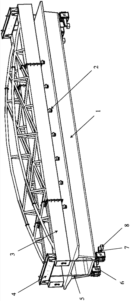
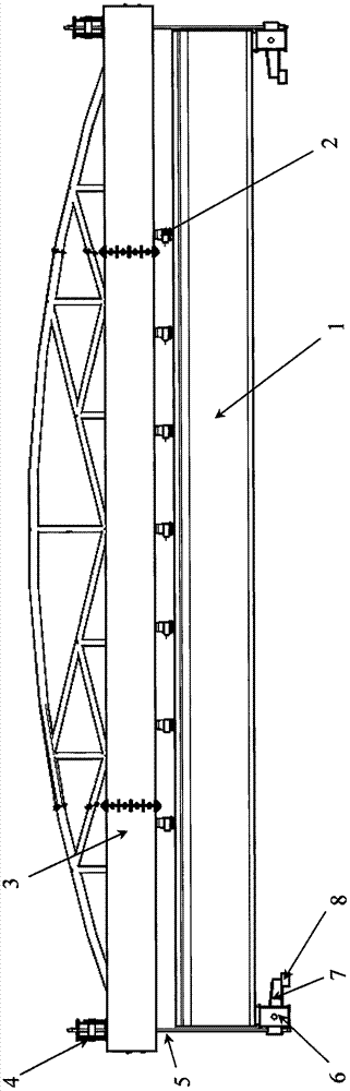
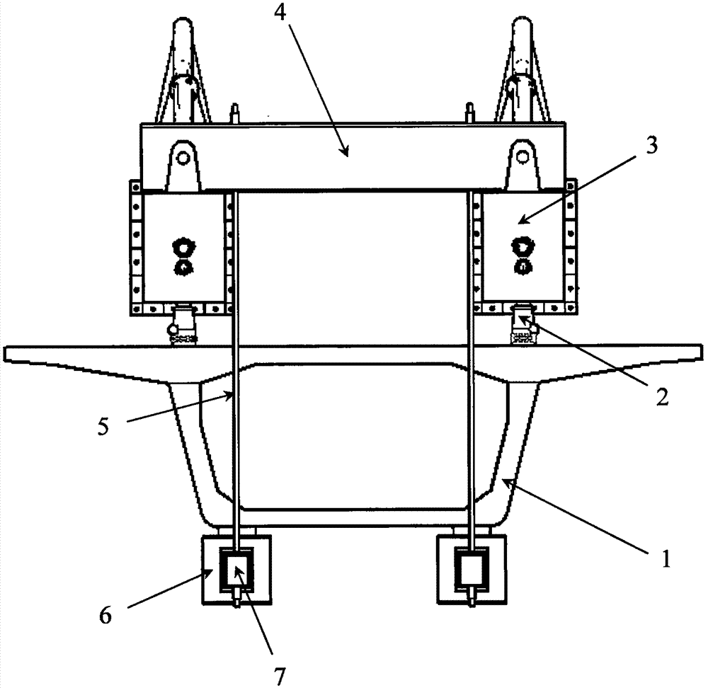
[0026] Such as Figure 1 to Figure 6 As shown, the prestressed steel pipe concrete self-balancing static load test bench for static load test of the present invention comprises a test beam 1, a jack 2, a reaction beam 3, an upper beam 4, a vertical tie rod 5, a support pier 6, Lever beam 7, ground reaction pier 8. The jack 2 is located between the test beam 1 and the reaction beam 3, the reaction beam 3 is located on the test beam 1, the upper beam 4 is arranged at both ends of the reaction beam 3, the vertical tie rod 5 is arranged at both ends of the upper beam 4, and the vertical tie rod 5 One end is connected to the upper beam 4, and the other end is connected to the rear end of the lever beam 7. The lever beam 7 penetrates the support pier 6 and is connected with the support pier 6 by a pin shaft. The front end of the lever beam 7 is connected to the ground reaction pier 8 contradict each other. The transmission path of the test loading force is: test jack 2 - reaction ...


PUM


Abstract

The invention relates to a bridge static load test device, in particular to a large-span simple supported beam prestress self-balancing type static load test table. The test table comprises a test beam, jacks, counter-force beams, upper cross beams, vertical pull rods, support piers, lever beams and ground counter-force piers. The counter-force beams are located on the test beam, the jacks are located between the counter-force beams and the test beam, the upper cross beams are located at the two ends of the counter-force beams, and the vertical pull rods are arranged at the two ends of the upper cross beams; the lower ends of the vertical pull rods are connected with the rear ends of the lever beams, the lever beams penetrate through the support piers through pin shaft connection, and the front ends of the lever beams are in contact with the ground counter-force piers to provide test counter-force. The counter-force beams are of a section spliced prestress structure so that a large quantity of materials can be saved. The situation that a bridge deck slab is drilled to allow the vertical pull rods to penetrate for testing is avoided. The test table is scientific in structure, economical and applicable, on-site fabricated beams can be transferred conveniently, the problem is solved that a foundation pit concrete heavy counter-force test table base is used in an existing 40 m beam and accordingly blow-up and second ploughing are caused, and the test table is suitable for static load tests of various spans and beam types.

Description

technical field [0001] The invention relates to a bridge static load test device, in particular to a prestressed steel pipe concrete self-balancing static load test bench for a static load test of a large-span simply supported box girder. Background technique [0002] Patent No. ZL 98248613.8 discloses a static load test device for prefabricated prestressed concrete simply supported beams, which uses universal rods to assemble truss beams to resist test loads, thereby realizing static load tests on prestressed concrete simply supported beams at the construction site. But this device has the following disadvantages: [0003] 1. The reaction frame is composed of universal rod truss beams. Due to the wide variety of rods and gusset plates, the assembly and disassembly are complicated and the cost is high. [0004] 2. The truss girder tensioning of the universal beam, due to the complex structure of the tension anchor point generated at the beam node, the application is limited...

Claims


Application Information

Patent Timeline
Patent Type & Authority Applications(China)
IPC IPC(8): G01N3/08
CPCG01N3/08
Inventor 孙金更姜会增张彩亮周兆春
Owner BEIJING HUAHENG NEW TECH DEV
Why Eureka
Try Eureka