Middle supporting wheel structure of horizontal bilateral glass edge grinding machine

An edger and supporting wheel technology, which is applied to the parts of grinding machine tools, machine tools suitable for grinding workpiece edges, grinding machines, etc., can solve the problems of low processing efficiency, inconvenient operation, high labor costs, and achieve tension And the effect of convenient replacement, reduced labor cost and high work efficiency

Active Publication Date: 2017-11-17
广东高力威机械科技有限公司
View PDF4 Cites 1 Cited by
  • Summary
  • Abstract
  • Description
  • Claims
  • Application Information

AI Technical Summary

Problems solved by technology

This manual intermediate supporting wheel support structure has the following defects: (1) low processing efficiency: when changing the width of the glass, it is necessary to stop the glass for edge grinding, and then grind after the intermediate supporting wheel is installed; (2) high labor cost: every Two operators are required to move the intermediate support wheel every time; (3) It is extremely inconvenient to operate: generally there are other equipment in the feeding and discharging directions of the edge grinding machine, which is extremely inconvenient when entering, and it is necessary to step on the machine bed structure. In the past; (4) Poor stability: When processing large glass plates, especially when the glass enters a part of the feed end, the force on the support roller 92 is unbalanced, causing the unstressed support roller pillar 91 at the discharge end to fall from the support roller beam 11. The glass is tilted up, causing the glass to be unable to move forward; (5) Inaccurate positioning: manual movement is more random and not accurate enough

Method used


Image

  • Middle supporting wheel structure of horizontal bilateral glass edge grinding machine
  • Middle supporting wheel structure of horizontal bilateral glass edge grinding machine
  • Middle supporting wheel structure of horizontal bilateral glass edge grinding machine

Examples


Embodiment Construction

[0034] The present invention will be further described below in conjunction with the accompanying drawings and embodiments.

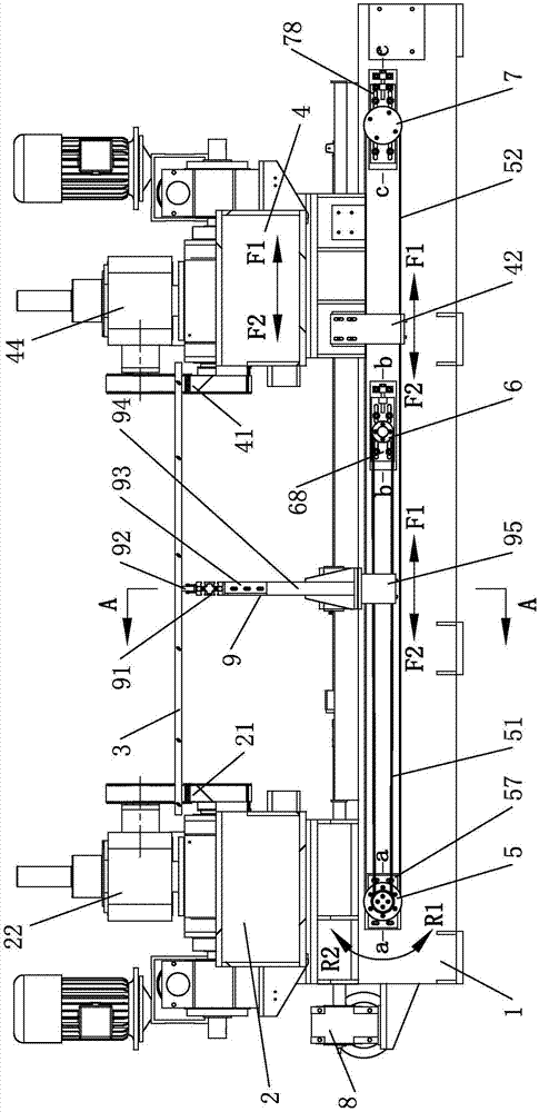
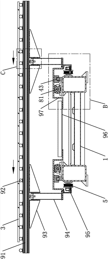
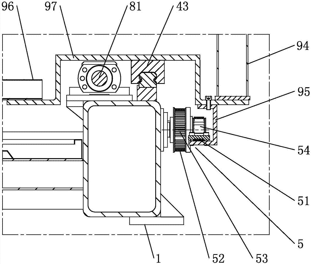
[0035] see Figure 1 to Figure 4 As shown, a horizontal glass double-edge grinding machine intermediate supporting wheel structure, including a bed assembly 1, a fixed side assembly 2, a moving side assembly 4, an intermediate supporting wheel assembly 9, and an assembly for controlling the moving side 4. The driving mechanism 8 that moves left and right. The fixed side assembly 2 and the moving side assembly 4 are respectively arranged on the left and right sides of the bed assembly 1. The fixed side assembly 2 and the moving side assembly 4 are used to hold the glass 3, And transport the glass 3 forward, the intermediate supporting roller assembly 9 is arranged on the bed assembly 1, and is located between the fixed side assembly 2 and the moving side assembly 4, and the intermediate supporting roller assembly 9 passes through the synchronous transmissi...


PUM


Abstract

The invention relates to a middle supporting wheel structure of a horizontal bilateral glass edge grinding machine. The middle supporting wheel structure comprises a machine tool body assembly, a fixed edge assembly, a moving edge assembly, a middle supporting wheel assembly and a driving mechanism used for controlling the moving edge assembly to move left and right; the fixed edge assembly and the moving edge assembly are arranged on the left side and the right side of the machine tool body assembly respectively and used for bearing glass and conveying the glass forwards, the middle supporting wheel assembly is arranged on the machine tool body assembly and located between the fixed edge assembly and the moving edge assembly and achieves linkage with the moving edge assembly through a synchronous transmission device, and the left-right moving speed of the middle supporting wheel assembly is smaller than that of the moving edge assembly. According to the structure, electrical adjustment is achieved by virtue of power of the moving edge assembly; in addition, linkage with the moving edge assembly is adjusted, it is guaranteed that the middle supporting wheel assembly can be located at the reasonable position between the fixed edge assembly and the moving edge assembly, the working efficiency is improved, and the labor cost is greatly reduced.

Description

technical field [0001] The invention relates to glass processing equipment, in particular to a middle supporting wheel structure of a horizontal double-sided glass edging machine. Background technique [0002] Glass needs to be edged before use or tempering. The glass moves on the conveying rails of the fixed side structure and the moving side structure. In order to reduce the deformation of the glass plane and affect the grinding quality, between the fixed structure and the moving structure Use intermediate rollers to support the glass. [0003] see Figure 8 and Figure 9 As shown, it is a horizontal double-sided glass edging machine with a manual intermediate supporting wheel support structure, which includes a bed assembly 1, a fixed side assembly 2, a moving side assembly 4, a driving mechanism 8, and an intermediate supporting wheel assembly 9 , the bed assembly 1 is provided with a bracket beam 11 pointing left and right (one end of the bracket beam 11 is fixed on t...

Claims


Application Information

Patent Timeline
Patent Type & Authority Applications(China)
IPC IPC(8): B24B9/08B24B9/10B24B41/00B24B41/06
CPCB24B9/08B24B9/10B24B9/102B24B41/00B24B41/06Y02P40/57
Inventor 范漪
Owner 广东高力威机械科技有限公司
Why Eureka
Try Eureka