
Optical fiber grating force tactile sensor, robot and mechanical fingertip thereof

A tactile sensor and optical fiber grating technology, applied in the field of sensors, can solve the problems of cumbersome manufacturing process of tactile sensors, no consideration of temperature compensation, etc., achieve the effect of compact structure, reduce acquisition error, and realize temperature compensation

Active Publication Date: 2017-11-17
WUHAN UNIV OF SCI & TECH
View PDF6 Cites 3 Cited by
  • Summary
  • Abstract
  • Description
  • Claims
  • Application Information

AI Technical Summary

Problems solved by technology

However, the manufacturing process of the above-mentioned tactile sensors based on the fiber grating principle is relatively cumbersome, and the problem of temperature compensation is not considered.

Method used


Image

  • Optical fiber grating force tactile sensor, robot and mechanical fingertip thereof
  • Optical fiber grating force tactile sensor, robot and mechanical fingertip thereof
  • Optical fiber grating force tactile sensor, robot and mechanical fingertip thereof

Examples


Embodiment Construction

[0027] The technical solutions of the present invention will be clearly and completely described below in conjunction with the accompanying drawings. Apparently, the described embodiments are some of the embodiments of the present invention, but not all of them. Based on the embodiments of the present invention, all other embodiments obtained by persons of ordinary skill in the art without making creative efforts belong to the protection scope of the present invention.

[0028] In the description of the present invention, it should be noted that the terms "center", "upper", "lower", "left", "right", "vertical", "horizontal", "inner", "outer" etc. The indicated orientation or positional relationship is based on the orientation or positional relationship shown in the drawings, and is only for the convenience of describing the present invention and simplifying the description, rather than indicating or implying that the referred device or element must have a specific orientation, ...


PUM


Abstract

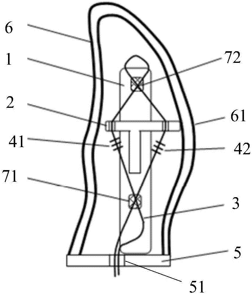
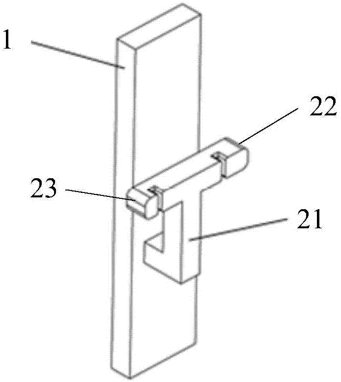
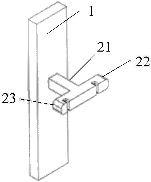
Provided are an optical fiber grating force tactile sensor, a robot and a mechanical fingertip thereof. The optical fiber grating force tactile sensor comprises a fixed plate, a transmission rod, a transmission optical fiber, a first optical fiber grating and a second optical fiber grating, wherein the fixed plate is of a strip-shaped structure and provided with an upper surface and a lower surface; the transmission rod is provided with a deformable cross beam, the transmission rod is fixed to the fixed plate through a fastening part arranged on the deformable cross beam, and the deformable cross beam of the transmission rod penetrates through the upper surface and the lower surface of the fixed plate and is suspended relative to the fixed plate; the deformable cross beam comprises a stress end for perceiving the external force and an auxiliary end located at the end opposite to the stress end; the head end of the transmission optical fiber sequentially penetrates through the stress end of the deformable cross beam, the upper surface of the fixed plate and the auxiliary end of the deformable cross beam from the lower surface of the fixed plate in a pre-tensioned mode, and then the head end and the tail end of the transmission optical fiber are fixed to the lower surface of the fixed plate; the first optical fiber grating is arranged on the portion, close to the lower portion of the auxiliary end of the deformable transmission fiber, of the transmission optical fiber; the second optical fiber grating is arranged on the portion, close to the lower portion of the stress end of the deformable cross beam, of the transmission optical fiber. The optical fiber grating force tactile sensor is compact in structure, can achieve temperature compensation and reduces collection errors.

Description

technical field [0001] The invention relates to the technical field of sensors, in particular to an optical fiber grating force tactile sensor, a robot and a mechanical fingertip thereof. Background technique [0002] With the rapid development of robot intelligence, the robot's force-tactile perception of external information is becoming more and more important. Robots with force-tactile information feedback can more accurately complete various fine and complex operations. Therefore, high-precision, high-reliability , The research and development of the force tactile sensor that can be integrated has been paid attention to by the scientific and technological circles. [0003] At present, it is reported that force tactile sensors are mostly designed based on electromagnetic signal components such as capacitors and strain gauges. These components have large zero point drift due to the influence of temperature and humidity, and weak electric signals are difficult to resist ele...

Claims


Application Information

Patent Timeline
IPC IPC(8): B25J13/08
CPCB25J13/084
Inventor 熊丽郭永兴蒋国璋孔建益李公法
Owner WUHAN UNIV OF SCI & TECH
Learn More