Supercharge Your Innovation With Domain-Expert AI Agents!

Movement execution mechanism for groove milling of artificial board and operating method of movement execution mechanism

A technology of executive mechanism and working method, which is applied in the direction of slotting machine, manufacturing tool, mortising machine, etc., can solve the problems affecting the accuracy of milling slot straightness, vibration and impact of wood-based panels, discontinuous working mode, etc. Achieve the effect of less impact, lower impact, lower complexity and cost

Active Publication Date: 2017-11-17
汉德智能科技(徐州)有限公司
View PDF8 Cites 0 Cited by
  • Summary
  • Abstract
  • Description
  • Claims
  • Application Information

AI Technical Summary

Problems solved by technology

[0003] For the assembly and aesthetic requirements of wood-based panels, it is often necessary to mill several open slots on its surface. The existing slot milling method uses a milling cutter controlled by a stepping motor to cooperate with a feedable work bed to mill slots one by one. This working method It is discontinuous, and the working bed is fed intermittently in the longitudinal direction, which will generate vibration and impact on the wood-based panel, which will have a great impact on its clamping stability, and will affect the accuracy conditions such as the straightness of the milling groove. At the same time, the vertical feed The milling cutter makes the structure of the lathe complex and increases the production cost

Method used


Image

  • Movement execution mechanism for groove milling of artificial board and operating method of movement execution mechanism
  • Movement execution mechanism for groove milling of artificial board and operating method of movement execution mechanism

Examples


Embodiment Construction

[0023] The following will clearly and completely describe the technical solutions in the embodiments of the present invention with reference to the accompanying drawings in the embodiments of the present invention. Obviously, the described embodiments are only some, not all, embodiments of the present invention. Based on the embodiments of the present invention, all other embodiments obtained by persons of ordinary skill in the art without making creative efforts belong to the protection scope of the present invention.

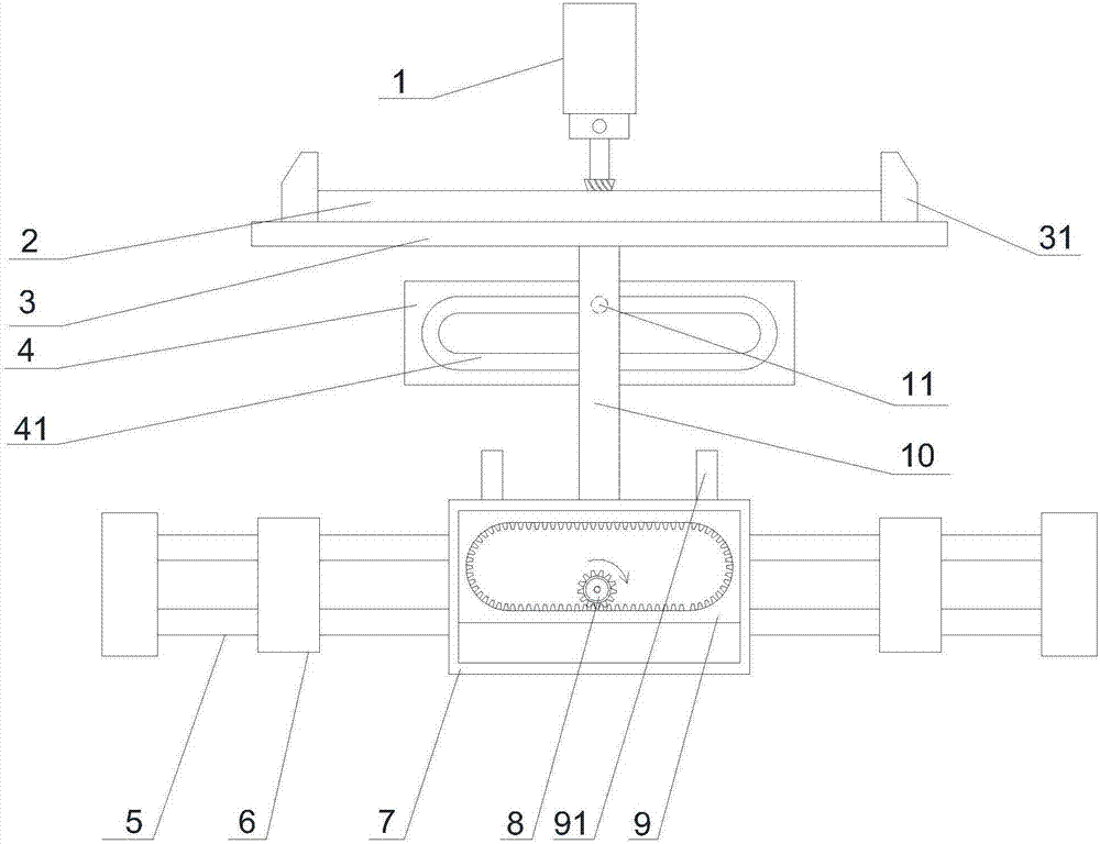
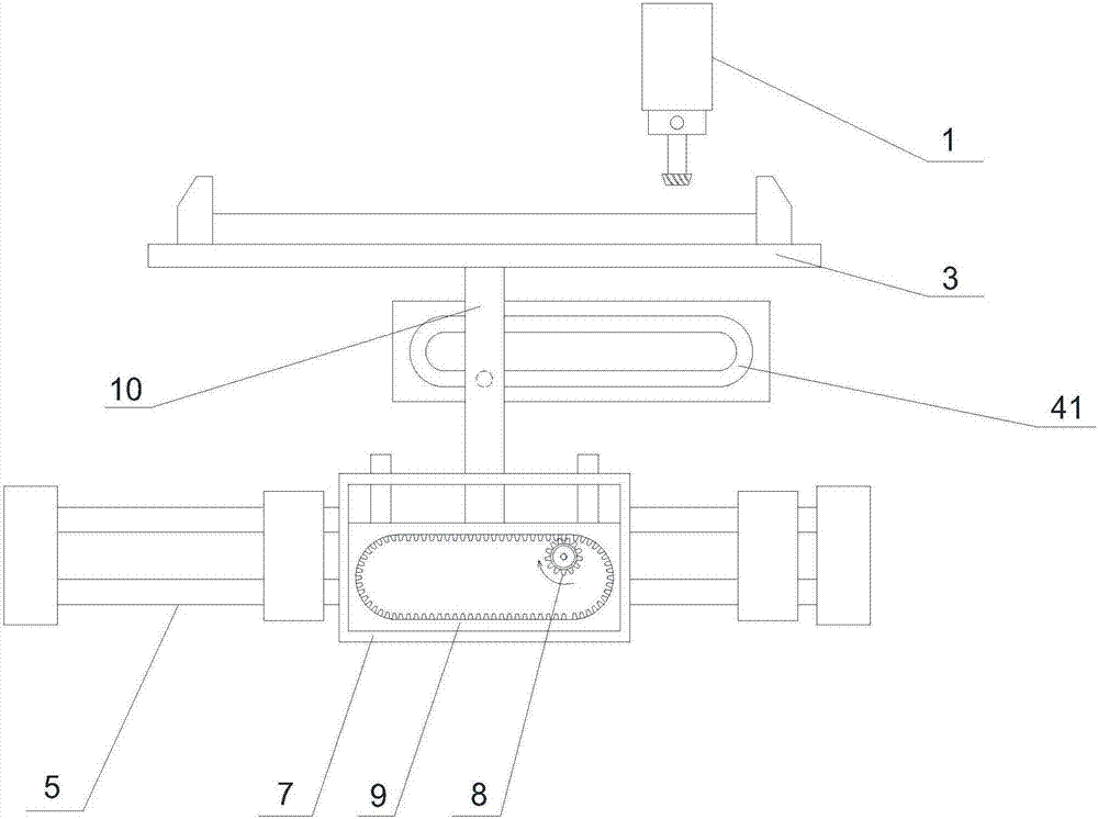
[0024] see Figure 1~2 , in the embodiment of the present invention, a wood-based panel groove milling motion actuator includes: an outer frame 7, an inner frame 9, a longitudinal control frame 4 and a work bed 3, and lateral guide rods 5 are fixedly arranged on the left and right sides of the outer frame 7, Transverse guide rod 5 is slidably arranged in the fixed sliding seat 6, and can move left and right with outer frame 7, and inner frame 9 is positioned i...


PUM


Abstract

The invention discloses a movement execution mechanism for groove milling of an artificial board. The execution mechanism for groove milling of the artificial board comprises an outer frame, an inner frame, a longitudinal control frame and a working bed. The left end of the inner frame makes contact with the left side of the outer frame, and the right end of the inner frame makes contact with the right side of the outer frame. Longitudinal guide rods are fixedly arranged on the inner frame and arranged in guide grooves located in the outer frame. A long kidney-shaped hollowed-out part is arranged in the inner frame, and a toothed groove structure is arranged on the inner wall of the hollowed-out part. The longitudinal control frame is fixedly arranged over the outer frame, a sliding groove consistent with the hollowed-out part of the inner frame in shape and size is formed in the longitudinal control frame. According to the execution mechanism for groove milling of the artificial board, the outer frame moves left and right to drive the artificial board to move so as to replace feeding movement of a milling cutter, the artificial board reciprocates continuously, and thus the system structure is more stable; the inner frame drives the artificial board to reciprocate up and down so as to replace longitudinal feeding and retreating of the milling cutter, so that impact to the milling cutter is reduced; and meanwhile, a milling cutter end control structure and system are simplified, and the complexity and cost of a lathe are reduced.

Description

technical field [0001] The invention relates to an industrial product processing equipment, in particular to an artificial board groove milling motion actuator and a working method thereof. Background technique [0002] Wood-based panels are boards or molded products that are made of wood or other non-wood plants, separated into various unit materials by certain mechanical processing, and glued with or without adhesives and other additives. It mainly includes three major categories of products: plywood, shaving (particle) board and fiberboard, with hundreds of extended products and deep-processed products. The birth of wood-based panels marks the beginning of the modern era of wood processing, which makes the process develop from simply changing the shape of wood to improving the properties of wood. This development not only involves all wood processing techniques, but also needs to absorb technologies in the fields of textiles and papermaking to form independent processing...

Claims


Application Information

Patent Timeline
Patent Type & Authority Applications(China)
IPC IPC(8): B27F5/02
CPCB27F5/02
Inventor 邵爱国
Owner 汉德智能科技(徐州)有限公司
Features
  • R&D
  • Intellectual Property
  • Life Sciences
  • Materials
  • Tech Scout
  • Unparalleled Data Quality
  • Higher Quality Content
  • 60% Fewer Hallucinations
Learn More