Block valve capable of being opened and closed reversely

A valve, reverse technology, applied in the field of reverse opening and closing cut-off valves, can solve the problems of poor sealing, valves cannot be closed tightly, large closing force, etc., achieve long service life, easy production and manufacturing, and reduce operation Effect

Pending Publication Date: 2017-11-17
四川固特阀门制造有限公司
View PDF4 Cites 1 Cited by
  • Summary
  • Abstract
  • Description
  • Claims
  • Application Information

AI Technical Summary

Problems solved by technology

This opening and closing method has the following defects: if the medium pressure is too large, the disc may move upward slightly due to the pressure of the medium, so that the valve may not be tightly closed, the sealing is not good, and the required closing force is large

Method used


Image

  • Block valve capable of being opened and closed reversely
  • Block valve capable of being opened and closed reversely
  • Block valve capable of being opened and closed reversely

Examples


Embodiment 1

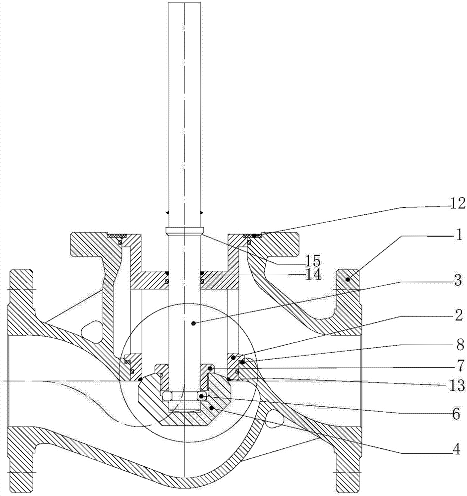
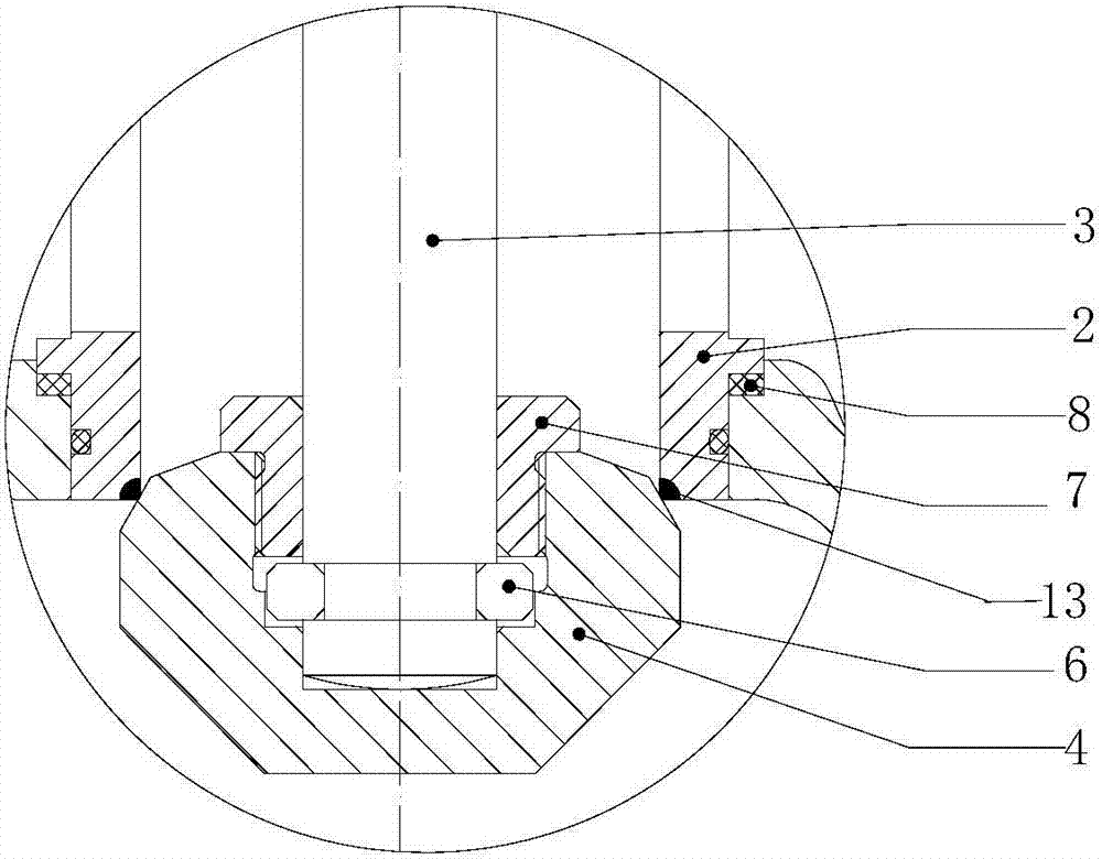
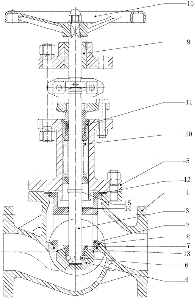
[0050] Reverse opening and closing cut-off valves, such as figure 1As shown, the reverse opening and closing cut-off valve includes a valve body 1, a valve seat 2, a valve stem 3, a valve disc 4, a split ring 6 and a valve disc cover 7; the valve seat 2 and the through hole in the middle of the valve body 1, the valve The rod 3 is arranged in the through hole of the valve body 1 and the valve seat 2 and can move up and down; the maximum width of the valve disc 4 is larger than the diameter of the internal through hole of the valve seat 2 and is located below the valve seat 2, and the middle part of the valve disc 4 is provided with a blind hole , used to connect with the valve stem 3; the split ring 6 is arranged in the ring groove of the valve stem 3, between the valve stem 3 and the valve disc 4, and the outer diameter of the split ring 6 is larger than the diameter of the valve stem 3; the valve The inside of the flap cover 7 is a through hole with a diameter smaller than t...

Embodiment 2

[0061] Reverse opening and closing cut-off valve, including valve body 1, valve seat 2, valve stem 3, valve disc 4 and valve disc cover 7, the inside of the valve disc cover 7 is a through hole, different from the embodiment 1, there is no split circle The ring 6, the disc cover 7, the disc 4 and the valve stem 3 are directly and detachably connected, such as through threaded connection, so as to connect the valve stem 3 and the valve disc 4 together, so that the valve stem 3 is up and down The movement can drive the valve clack 4 to move up and down.

Embodiment 3

[0063] The reverse opening and closing cut-off valve is different from Embodiment 2 in that there is no disc cover 7, but the valve disc and the valve stem are fixedly connected together by welding, so that the valve stem 3 and the valve disc 4 are connected together. Together, the up and down movement of the valve rod 3 can drive the up and down movement of the valve disc 4 .

[0064] In this case, there is no gap between the blind hole in the valve disc 4 and the valve stem 3, or there is no gap between the contact upper part of the valve disc 4 and the valve stem 3, so as to ensure that the particles in the medium will not be deposited In the depression of the valve clack, the lower part of the valve stem 3 is not welded with the valve clack 4, and the lower end surface of the valve stem 3 is not necessarily welded to the valve clack 4 either. Or, it is also possible that the lower end surface of the valve stem 3 is welded to the valve disc 4, and the upper part or all of t...


PUM


Abstract

The invention provides a reverse opening and closing cut-off valve, including a valve body, a valve seat, a valve stem and a valve disc; the valve seat and a through hole in the middle of the valve body, and the valve stem is arranged in the through hole of the valve body and the valve seat The center can move up and down; the valve seat is arranged on the valve body, the maximum width of the valve disc is greater than the diameter of the internal through hole of the valve seat and is located below the valve seat, and the middle part of the valve disc is provided with The blind hole is used for connecting with the valve stem. The reverse opening and closing cut-off valve of the present invention has a novel structure and is easy to open and close; the sealing surface is set on the valve seat, and the valve seat is removable, which can realize online maintenance; an upper seal is added to prevent the medium from entering the bellows when the valve is opened Cavity; the sealing surface of the valve is a linear sealing surface, and the direction is downward, avoiding the abnormal damage of the sealing surface caused by the accumulation of particles in the medium, effectively prolonging the service life of the valve; reducing parking and replacement, and reducing the labor intensity of the operator on site , Put an end to the damage caused by the leakage of the valve to the environment and the person.

Description

technical field [0001] The invention relates to a shut-off valve, in particular to a reverse opening and closing shut-off valve. Background technique [0002] In petroleum, chemical or other systems, in order to prevent medium leakage, valves are essential parts. [0003] In the prior art, the cut-off valve is opened by the upward movement of the valve disc, and the valve is closed by the downward movement of the valve disc, such as the Chinese utility model patent with the announcement number CN86208085UD, the Chinese utility model patent with the announcement number CN2114739U, and the publication number is The stage valve disclosed in the Chinese invention patent application document of CN1105741A, the Chinese utility model patent with the announcement number of CN2338553Y and the Chinese invention patent application document with the publication number of CN102818055A all open the valve by moving the valve disc upward, and the valve disc moves downward And close the val...

Claims


Application Information

Patent Timeline
Patent Type & Authority Applications(China)
IPC IPC(8): F16K1/48F16K1/00F16K1/42F16K41/02
CPCF16K1/48F16K1/00F16K1/42F16K41/02
Inventor 陈顺强杨杰雷文平陈兴安
Owner 四川固特阀门制造有限公司
Why Eureka
Try Eureka