Rotor punching sheet, rotor, and permanent magnet motor

A technology of rotor punching and rotor, which is applied in the field of rotor and a permanent magnet motor, can solve problems such as motor torque ripple, and achieve the effects of reducing inductance fluctuation, reducing vibration and noise, and high efficiency characteristics

Inactive Publication Date: 2017-11-17
GUANGDONG WELLING ELECTRIC MACHINE MFG +1
View PDF7 Cites 2 Cited by
  • Summary
  • Abstract
  • Description
  • Claims
  • Application Information

AI Technical Summary

Problems solved by technology

[0003] The purpose of the present invention is to overcome the problems of motor torque pulsation and vibration noise in the prior art, and to provide a rotor punch, rotor and permanent magnet motor. After using the rotor punch, the direction of the magnetic circuit can be effectively improved, Reduces torque ripple of permanent magnet motors, thereby reducing vibration and noise

Method used


Image

  • Rotor punching sheet, rotor, and permanent magnet motor
  • Rotor punching sheet, rotor, and permanent magnet motor

Examples


Embodiment Construction

[0023] In the present invention, it should be understood that the directions or positional relationships indicated by the terms "inner", "outer", "axial", "radial", "circumferential", etc. are based on the directions or positions shown in the drawings. The relationship also corresponds to the actual orientation or positional relationship. It is only for the convenience of describing the present invention and simplifying the description, rather than indicating that the device or component must have a specific orientation, be constructed and operated in a specific orientation, and therefore cannot It is understood as a limitation of the present invention.

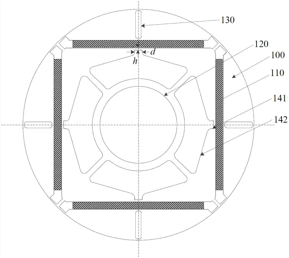
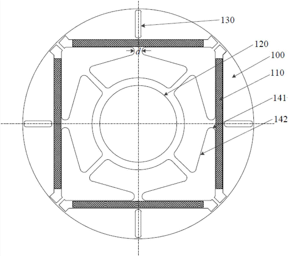
[0024] The present invention provides a rotor punch. The rotor punch is provided with a shaft hole 120 in the center and a plurality of permanent magnet slots 110 are arranged at intervals around the shaft hole 120. An inner magnetic isolation hole 141 is arranged between the shaft holes 120, and the inner magnetic isolation hol...


PUM


Abstract

The invention relates to the field of motors, and discloses a rotor punching sheet, a rotor, and a permanent magnet motor. The center of the rotor punching sheet is provided with an axis hole (120), and is provided with a plurality of permanent magnet slots (110) which are arranged around the axis hole (120) at intervals. Internal magnetic isolating holes (141) are disposed between the permanent magnet slots (110) and the axis hole (120), and the internal magnetic isolating holes (141) and the permanent magnet slots (110) have the same geometric center symmetric line. The geometric center symmetric line radially extends along the rotor punching sheet, and the minimum distance between the internal magnetic isolating holes (141) and the permanent magnet slots (110) is not greater than 1mm. When the rotor punching sheet is used, the direction of a magnetic path can be improved effectively, and the torque ripple of the permanent magnet motor is reduced, thereby reducing the vibration noise.

Description

Technical field [0001] The invention relates to the technical field of electric motors, in particular to a rotor punching sheet, a rotor and a permanent magnet motor. Background technique [0002] For existing permanent magnet motors, most permanent magnets are installed with a built-in rotor magnetic circuit structure, which has good mechanical strength, but there are problems such as high reluctance torque, torque ripple, and large vibration and noise of the motor. In view of this, there is also a design in the prior art by providing an outer magnetic isolation hole between the permanent magnet and the outer edge of the rotor. For example, the application number CN201310164969.8 and CN201610402935.1 proposed in the built-in permanent magnet and the outer edge of the rotor. Magnetic isolation slots are provided between the edges to improve the magnetic circuit direction of the motor, but the effect of reducing the torque ripple and vibration noise of the motor is limited. Theref...

Claims


Application Information

Patent Timeline
Patent Type & Authority Applications(China)
IPC IPC(8): H02K1/27
CPCH02K1/2706H02K2213/03
Inventor 陈金涛吴迪武谷雨诸自强
Owner GUANGDONG WELLING ELECTRIC MACHINE MFG
Why Eureka
Try Eureka