A high cleanliness dust removal equipment

A dust removal equipment and high cleanliness technology, which is applied in the field of high cleanliness dust removal equipment, can solve the problems of high cost and general dust removal effect, achieve the effect of improving the effect, avoiding excessive water vapor, and improving the filtering effect

Inactive Publication Date: 2019-11-15
太仓市除尘设备厂
View PDF5 Cites 4 Cited by
  • Summary
  • Abstract
  • Description
  • Claims
  • Application Information

AI Technical Summary

Problems solved by technology

[0003] Most of the existing dust removal equipment on the market use fans or electrostatic dust collectors. During the working process, the dust removal effect is average, and the discharged gas will still be mixed with a lot of particles, and some large-scale dust removal equipment has the best dust removal effect in time. Very good, but its cost is high, so the existing dust removal equipment needs to be improved

Method used


Image

  • A high cleanliness dust removal equipment
  • A high cleanliness dust removal equipment

Examples


Embodiment 1

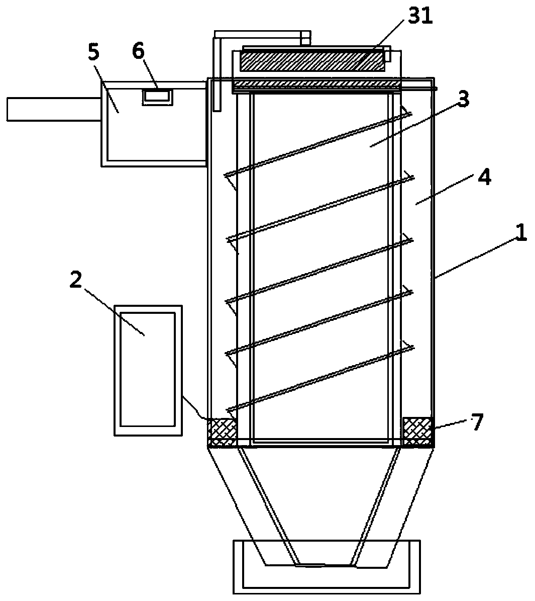
[0022] As shown in the figure, a high-cleanliness dust removal equipment includes: a housing 1 and a control device 2, the housing 1 is provided with a set of air inlets and an air outlet, and the housing 1 is provided with an inner cavity 3 and an outer cavity 4, the air inlet is provided with a gas collection chamber 5, the inner cavity 3 is located inside the outer cavity 4, a rotating mechanism 41 is provided in the outer cavity 4, and the inner cavity The outlet of the body 3 is provided with a first filter mechanism 31 , the gas collection chamber 5 is provided with a gas detection mechanism 6 , and the rotation mechanism 41 , the first filter mechanism 32 and the gas detection mechanism 6 are all connected to the control device 2 .

[0023] In this embodiment, the outlet of the inner cavity 3 is provided with an electric control door and a ventilation pipe, and the ventilation pipe is connected with the outer cavity, and the ventilation pipe is provided with an electric ...

Embodiment 2

[0030] As shown in the figure, a high-cleanliness dust removal equipment includes: a housing 1 and a control device 2, the housing 1 is provided with a set of air inlets and an air outlet, and the housing 1 is provided with an inner cavity 3 and the outer cavity 4, the air inlet is provided with a gas collection chamber 5, the inner cavity 3 is arranged inside the outer cavity 4, a rotating mechanism 41 is provided in the outer cavity 4, and the inner cavity The outlet of the body 3 is provided with a first filter mechanism 31 , the gas collection chamber 5 is provided with a gas detection mechanism 6 , and the rotation mechanism 41 , the first filter mechanism 32 and the gas detection mechanism 6 are all connected to the control device 2 .

[0031] In this embodiment, the outlet of the inner cavity 3 is provided with an electric control door and a ventilation pipe, and the ventilation pipe is connected with the outer cavity, and the ventilation pipe is provided with an electri...


PUM


Abstract

The invention discloses a high-cleanliness dust removal device, comprising: a housing and a control device, the housing is provided with a group of air inlets and an air outlet, and the housing is provided with an inner cavity and an outer cavity, The air inlet is provided with a gas collection chamber, the inner cavity is arranged inside the outer cavity, the outer cavity is provided with a rotating mechanism, and the outlet of the inner cavity is provided with a first filter mechanism, so A gas detection mechanism is arranged in the gas collection chamber, and the rotation mechanism, the first filtering mechanism and the gas detection mechanism are all connected with the control device. In the present invention, a gas collection chamber is arranged at the air inlet, and the impurity content and concentration in the gas are detected by a gas detection mechanism, and the time and frequency of dust removal are determined according to the detection results. It can form a downward airflow, use natural gravity to achieve double separation, and then perform deep filtration through the filtering mechanism, greatly improving its filtering effect.

Description

technical field [0001] The invention belongs to the field of dust removal equipment, in particular to a high-cleanliness dust removal equipment. Background technique [0002] With the rapid development of social economy, people's living standards and quality of life are constantly improving, and whether it is production or life, people's rhythm is constantly accelerating, and most of them have realized intelligence and automation in both production and life. , and the quality requirements for the environment are getting higher and higher, which promotes the generation of dust removal equipment. [0003] Most of the existing dust removal equipment on the market use fans or electrostatic dust collectors. During the working process, the dust removal effect is average, and the discharged gas will still be mixed with a lot of particles, and some large-scale dust removal equipment has the best dust removal effect in time. Very good, but its cost is relatively high, so the existin...

Claims


Application Information

Patent Timeline
Patent Type & Authority Patents(China)
IPC IPC(8): B01D50/00
CPCB01D50/10
Inventor 陆维光
Owner 太仓市除尘设备厂
Why Eureka
Try Eureka