A main traction device of a bag making machine

A technology of traction device and bag making machine, which is applied in the field of traction device, can solve the problems of low installation accuracy, unreliable locking, and inaccurate size, and achieve the goals of reducing the difficulty of installation operation, convenient replacement of rubber rollers, and ensuring installation accuracy Effect

Active Publication Date: 2020-04-14
SINOMECH CORP
View PDF15 Cites 0 Cited by
  • Summary
  • Abstract
  • Description
  • Claims
  • Application Information

AI Technical Summary

Problems solved by technology

[0002] The traction device of the bag making machine with spout packaging bags has two characteristics. One is that its traction pressing rubber roller must adopt a structure with coaxial multi-rollers and the lateral position of the rubber rollers can be adjusted. Now the structure is a core Adding multiple rubber rollers on the shaft has the following problems: it is inconvenient to replace the rubber rollers, the locking is unreliable, the installation accuracy is low, the bending resistance of the rubber roller mandrel is low, and an additional support mechanism needs to be added; Because the film has no wrap angle, it is easy to slip, so the existing structure of the traction roller mostly uses rubber rollers. The problem it brings is that the traction rubber roller is easy to deform and the size is not accurate, so the traction effect is not good, and the roller The surface wears quickly, and the traction roller needs to be replaced regularly

Method used


Image

  • A main traction device of a bag making machine
  • A main traction device of a bag making machine
  • A main traction device of a bag making machine

Examples


Embodiment Construction

[0022] The present invention will be further described below in conjunction with the accompanying drawings of the description.

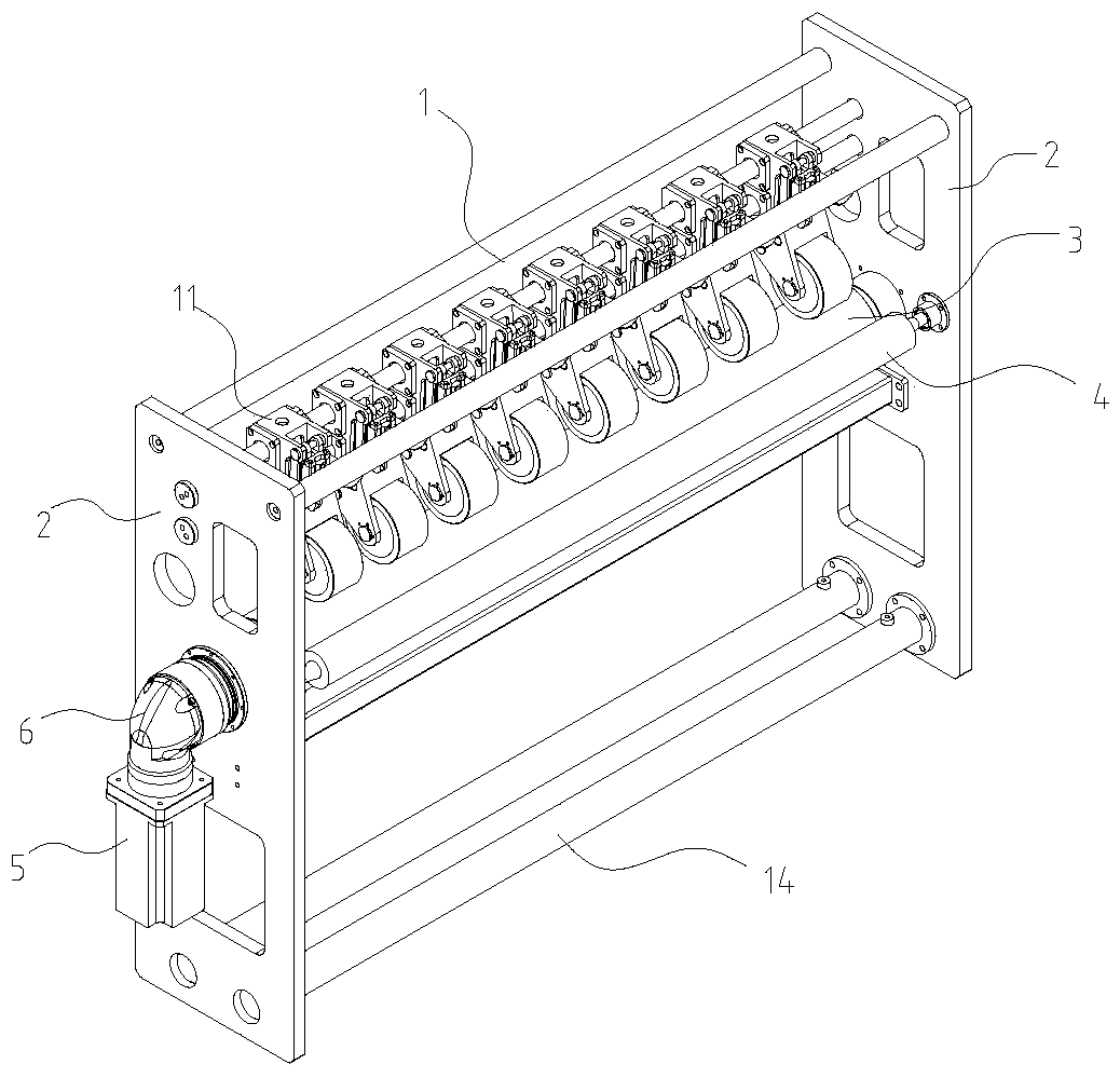
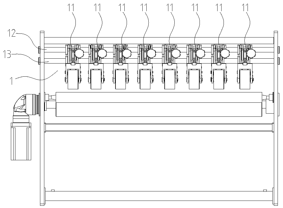
[0023] like figure 1 , 2 As shown, a main traction device of a bag making machine includes a traction roller 3, a driving mechanism for driving the traction roller, a coaxial multi-pressure rubber roller swing arm mechanism 1 located above the traction roller 3, wall panels 2 on both sides and a The guide roller 4 in front of the traction roller 3 . The driving mechanism is fixed on the outer surface of the wall panels 2, and the traction roller 3 and the coaxial multi-pressure rubber roller swing arm mechanism 1 are located between the two wall panels 2.

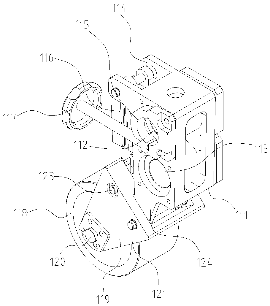
[0024] like image 3 As shown, the coaxial multi-pressure rubber roller swing arm mechanism 1 includes an upper slide bar 12 , a lower slide bar 13 and several swing pressure roller assemblies 11 hung on the upper slide bar 12 . The two ends of the upper slide bar 12 and the lower slide bar 13...


PUM


Abstract

A main pulling device of a bag making machine comprises a pull roll, a driving mechanism for driving the pull roll, and a coaxial multi-dandy roll swinging arm mechanism which is positioned above the pull roll, wherein the pull roll is a steel roll of which the surface is provided with a ceramic layer; the coaxial multi-dandy roll swinging arm mechanism comprises an upper slide rod, a lower slide rod, and a plurality of swinging pressing roll assemblies which are mounted on the upper slide rod and the lower slide rod; each swinging pressing roll assembly comprises a bracket, a swinging arm which is hinged with each bracket, a dandy roll which is pivoted to each swinging arm, and a cylinder for driving each swinging arm to swing; a first through hole through which the upper slide rod passes is formed in each bracket; a locking seat is arranged at the first through hole in one side of each bracket; a second through hole through which the lower slide rod passes is formed in each bracket. According to the device, the brackets are strictly processed according to a drawing by a processing center based on the mounting standard of the swinging arms, the cylinder and a slide sleeve, and each bracket is provided with the same hole size. Therefore, the difficulty in mounting operation is reduced, and the mounting accuracy is ensured.

Description

technical field [0001] The invention relates to a traction device, in particular to a main traction device of a bag making machine. Background technique [0002] The traction device of the bag making machine with spout packaging bags has two characteristics. One is that its traction pressing rubber roller must adopt a structure with coaxial multi-rollers and the lateral position of the rubber rollers can be adjusted. Now the structure is a core Adding multiple rubber rollers on the shaft has the following problems: it is inconvenient to replace the rubber rollers, the locking is unreliable, the installation accuracy is low, the bending resistance of the rubber roller mandrel is low, and an additional support mechanism needs to be added; Because the film has no wrap angle, it is easy to slip, so the existing structure of the traction roller mostly uses rubber rollers. The problem it brings is that the traction rubber roller is easy to deform and the size is not accurate, so t...

Claims


Application Information

Patent Timeline
Patent Type & Authority Patents(China)
IPC IPC(8): B31B70/74
Inventor 黄顺利
Owner SINOMECH CORP
Why Eureka
Try Eureka