A Compensation Method for Robot End Position

A technology of end position and compensation method, applied in the direction of instruments, simulators, computer control, etc., can solve the problems of poor data statistics and calculation accuracy, reduced work accuracy, complicated calculation process, etc., to achieve good versatility, improve accuracy and The effect of error compensation operation efficiency and high degree of operation automation

Active Publication Date: 2018-07-31
北京微链道爱科技有限公司
View PDF2 Cites 0 Cited by
  • Summary
  • Abstract
  • Description
  • Claims
  • Application Information

AI Technical Summary

Problems solved by technology

[0002] As robotic equipment is used in daily life and work, robotic equipment has been used more and more, but in actual use, it is found that with the operation of the robot and the interference of the external environment, the robot will be formed to varying degrees during the operation process. Errors, and finally accumulate the errors formed in each link at the end of the working parts of the robot, and eventually lead to the phenomenon of a decrease in the accuracy of the work during the operation of the robot. Currently, in the process of robot operations, when compensating for errors, it is mainly based on The end point of the robot end or the end face of the processing equipment is used as the statistical origin of error compensation, and then the running coordinate system is established, and at the same time, the stroke error at the end of the robot is eliminated by combining the mechanical transmission ratio, wear rate and other parameters, and then repaired, so as to improve the working accuracy of the robot Although this compensation method can meet the needs of compensation operations, the amount of data calculation is large, the calculation process is complicated, the calculation efficiency is low, and the data statistics and calculation accuracy are relatively poor, which cannot effectively meet the needs of actual use. Therefore, for this There is an urgent need to develop a robot end position compensation method to meet the needs of actual use

Method used


Image

  • A Compensation Method for Robot End Position

Examples


Embodiment Construction

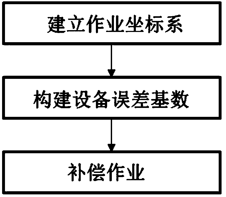
[0013] Such as figure 1 Shown, a kind of robot end position compensation method is characterized in that, described robot end position compensation method comprises the following steps:

[0014] The first step is to establish a work coordinate system. Before the robot runs, according to the robot’s running trajectory, first establish a three-dimensional coordinate system of the robot’s end running trajectory with the position of the robot’s working end equipment in the state of stop and reset as the origin, and embed the robot’s end running trajectory into In the coordinate system, construct several control nodes along the running track;

[0015] The second step is to construct the equipment error base. After the first step is completed, the time parameter is introduced into the three-dimensional coordinate system of the robot end trajectory, and the specific time value when the robot end passes through each control node according to its operation trajectory is calculated. Th...


PUM


Abstract

The invention discloses a robot end position compensation method, comprising three steps of establishing a work coordinate system, establishing an equipment error base, and performing compensation operation. The method is simple in system structure, high in operation automation degree, and good in universality. On one hand, error detection in a robot operation process and working efficiency of compensation operation can be effectively improved, and on the other hand, accuracy of error detection operation data statistics and calculation in the robot operation process can be effectively simplified, and data operation process is effectively simplified, and operation amount is reduced, so as to greatly improve accuracy of robot error compensation work and error compensation working efficiency.

Description

technical field [0001] The invention relates to a method for compensating the end position of a robot, which belongs to the technical field of robot equipment. Background technique [0002] As robotic equipment is used in daily life and work, robotic equipment has been used more and more, but in actual use, it is found that with the operation of the robot and the interference of the external environment, the robot will be formed to varying degrees during the operation process. Errors, and finally accumulate the errors formed in each link at the end of the working parts of the robot, and eventually lead to the phenomenon of a decrease in the accuracy of the work during the operation of the robot. Currently, in the process of robot operations, when compensating for errors, it is mainly based on The end point of the robot end or the end face of the processing equipment is used as the statistical origin of error compensation, and then the running coordinate system is established...

Claims


Application Information

Patent Timeline
Patent Type & Authority Patents(China)
IPC IPC(8): G05B19/404
CPCG05B19/404G05B2219/35408
Inventor 邵根顺
Owner 北京微链道爱科技有限公司
Why Eureka
Try Eureka