Supercharge Your Innovation With Domain-Expert AI Agents!

Heat exchanging water tank of water fountain

A technology for exchanging hot water tanks and drinking fountains, which is applied in beverage preparation devices, household appliances, applications, etc., can solve the problems of long cooling time, easy to be polluted by the external environment, and cooling speed affected by heat dissipation performance, so as to reduce energy and improve energy saving. effect of effect

Inactive Publication Date: 2017-11-24
洪伟
View PDF0 Cites 2 Cited by
  • Summary
  • Abstract
  • Description
  • Claims
  • Application Information

AI Technical Summary

Problems solved by technology

However, boiled water needs to be boiled and cooled to obtain drinking water, and the boiled drinking water has a higher temperature, and its own heat dissipation performance affects the cooling speed when placed at room temperature, and the cooling time is longer
In addition, boiled water placed at room temperature is easily polluted by the external environment during the placement process, which is not conducive to human health.

Method used


Image

  • Heat exchanging water tank of water fountain
  • Heat exchanging water tank of water fountain
  • Heat exchanging water tank of water fountain

Examples


Embodiment 1

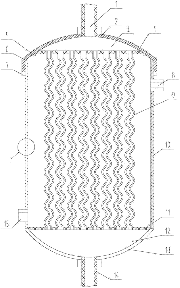
[0023] Embodiment 1: A water exchange tank for a water dispenser, including a box body 10, the box body 10 is cylindrical, its top is an arc-shaped cover 2, and its bottom is an arc-shaped base 13 integrated with it. The interior includes the hot water dispersion chamber 3 formed by the upper fixed plate 4 and the arc-shaped cover body 2, the hot water collection chamber 12 composed of the lower fixed plate 11 and the arc-shaped base 3, the hot water collection chamber 12 and the hot water dispersion chamber 3 A spiral heat exchange tube 9 is installed between them. The two ends of the heat exchange tube 9 are straight pipes, and the middle part is a spiral pipe. Connect with threaded connection. The upper and lower ends of the box body 10 are respectively connected with a hot water inlet pipe 1 and a hot water outlet pipe 14, and the hot water inlet pipe 1 and the hot water outlet pipe 14 respectively penetrate the hot water dispersion chamber 3 and the hot water collection c...

Embodiment 2

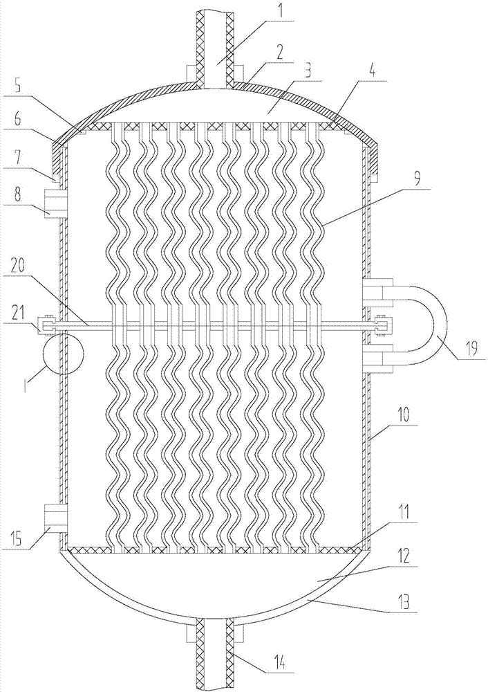
[0024] Embodiment 2: A water exchange tank for a water dispenser, wherein the box body 10 is divided into upper and lower parts connected by a middle partition 20 and a buckle 21, and the middle partition 20 is provided with an upper fixing plate 4 and a lower The through holes at the same position of the fixing plate 11 and the heat exchange tubes 9 are installed at the through holes. The structures and connections of the remaining parts are the same as those described in any of the foregoing embodiments.

[0025] In view of the foregoing embodiments, when the application is in use, its working process and principle are as follows:

[0026] The purpose of the heat exchange tank of the water dispenser of the present invention is to add a heat exchange box to the water dispenser so that the boiled drinking water can exchange heat with the original cold water in the water dispenser through pipes, so as to reduce the boiling time. The temperature of plain boiled water obtains th...


PUM


Abstract

The invention discloses a water exchange tank for a water dispenser, which belongs to the field of household electrical appliances and is used to make the water dispenser produce a cold water tank that is suitable for drinking. The upper end of the arc-shaped cover is equipped with a through hot water inlet pipe, and the lower end of the box body is an arc-shaped base integrated with the box body, and a through-hole hot water outlet pipe is installed on the arc-shaped base; From top to bottom, there are hot water dispersion chamber, upper fixed plate, heat exchange tube, lower fixed plate, hot water collection chamber, and the upper and lower ends of the box are respectively opened with cold water inlet and cold water outlet, and the cold water inlet and cold water outlet are connected. The box body is connected with the inner cavity of the box body. In view of the above technical solution, the present invention can be used in water dispensers to exchange heat between hot water and cold water in the water dispenser through pipelines to form boiled water suitable for direct consumption by people, and can reduce the energy consumed by the water dispenser to heat drinking water.

Description

technical field [0001] The invention belongs to the field of household electrical appliances, and in particular relates to a water exchange tank for a water dispenser used to produce plain boiled water for direct drinking. Background technique [0002] Plain boiled water, as the most frequently consumed liquid beverage in daily life, not only provides the necessary circulation substances for people's body, but also attracts the attention of health care professionals because it does not contain any added ingredients. But boiled water needs to boil drinking water and cool it down, and the drinking water after boiling has a higher temperature, and its own heat dissipation performance at room temperature affects the cooling speed, and the cooling time is longer. In addition, boiled water placed at room temperature is easily polluted by the external environment during the placement process, which is not conducive to human health. Contents of the invention [0003] The object o...

Claims


Application Information

Patent Timeline
IPC IPC(8): A47J31/44
CPCA47J31/4403
Inventor 洪伟孙敬赵秀宏高建文张春田田浩张渤张衡米飞
Owner 洪伟
Features
  • R&D
  • Intellectual Property
  • Life Sciences
  • Materials
  • Tech Scout
  • Unparalleled Data Quality
  • Higher Quality Content
  • 60% Fewer Hallucinations
Learn More