
Pipe bending device for air conditioner production

A technology of air-conditioning condenser and pipe bending device, which is applied in the direction of feeding device, positioning device, storage device, etc., which can solve the problem of the inability to adjust the bending angle of copper pipes, the inability to realize double-head bending at the same time, and affect the bending quality of copper pipes and other problems, to achieve good limit clamping effect, improve limit clamping effect, and high reliability

Inactive Publication Date: 2017-11-24
柴永朋
View PDF0 Cites 1 Cited by
  • Summary
  • Abstract
  • Description
  • Claims
  • Application Information

AI Technical Summary

Problems solved by technology

The material of the condenser is generally carbon steel, stainless steel and copper. When the carbon steel tube sheet is used as a cooler, the welds between the tube sheet and the tube tubes often have corrosion leakage, and the leakage will enter the cooling water system. Cause environmental pollution and waste of materials
[0003] In the prior art, there are still many deficiencies in the bending device for condenser production. When it is bent, it has a poor fixing effect on the copper tube, and it is prone to deviation of the copper tube, which seriously affects the bending of the copper tube. At the same time, the existing bending device for condenser production cannot realize double-head bending at the same time, and the work efficiency is low. The existing bending device for condenser production cannot adjust the bending angle of the copper tube during the bending process. The use is limited, so there is an urgent need for a bending device for the production of air-conditioning condensers to solve the above-mentioned problems

Method used


Image

  • Pipe bending device for air conditioner production
  • Pipe bending device for air conditioner production
  • Pipe bending device for air conditioner production

Examples


Embodiment Construction

[0022] In order to make the technical means, creative features, goals and effects achieved by the present invention easy to understand, the present invention will be further described below in conjunction with specific embodiments.

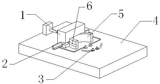
[0023] see Figure 1-Figure 4 , the present invention provides a technical solution: a pipe bending device for air-conditioning condenser production, including a device main body, a limit clamping mechanism 1, a double-head bending mechanism 2 and a bending angle adjustment mechanism 3, and the device main body includes a workbench 4. The semicircular block 5 and the annular groove 6, the semicircular block 5 is fixed on the upper end surface of the workbench 4, and the annular groove 6 is provided in the middle of the annular side of the semicircular block 5.

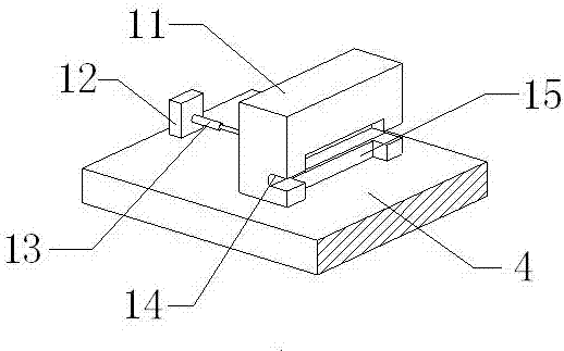
[0024] The limit clamping mechanism 1 is arranged on the left side of the semicircle block 5, the limit clamping mechanism 1 includes a movable block 11, a fixed plate 12, an electric tele...


PUM


Abstract

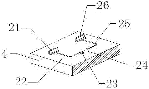
The invention provides a pipe bending device for the production of an air conditioner condenser, which includes a movable block, a fixed plate, an electric telescopic rod, a limit groove, a notch, a nut 1, an arc chute 1, a threaded rod 1, a threaded rod 2, a circle Arc chute 2 and nut 2, the limit groove is set on the right side of the front face of the movable block, and the limit groove communicates with the notch, and the left end of the electric telescopic rod is installed on the right end face of the fixed plate. This design improves the For the limited clamping effect of the copper pipe, the lower end of the threaded rod is assembled in the arc chute 1, the annular side of the threaded rod 1 is equipped with the nut 1, and the lower end of the threaded rod 2 is assembled in the arc chute Inside, the ring side of the threaded rod 2 is equipped with a nut 2. This design realizes the purpose of adjusting the bending angle of the copper pipe in the present invention. Tuning, good stability and high reliability.

Description

technical field [0001] The invention relates to a bent pipe device for production of an air conditioner condenser, which belongs to the field of condenser production equipment. Background technique [0002] Condenser (Condenser), a component of the refrigeration system, is a type of heat exchanger that can convert gas or vapor into liquid, and transfer the heat in the tube to the air near the tube in a very fast manner. It is one of the key equipment in the refrigeration system. The commonly used cooling media are water and air. According to the cooling (condensing) medium and heat transfer mechanism, it can be divided into air-cooled, water-cooled and evaporative. According to the shape and structure of the heat transfer surface, it can be divided into tube type, plate type and other structures. The working process of the condenser is an exothermic process, so the temperature of the condenser is relatively high. The material of the condenser is generally carbon steel, s...

Claims


Application Information

Patent Timeline
Patent Type & Authority Applications(China)
IPC IPC(8): B21D7/06B21D7/16B21D43/00B21D53/02
CPCB21D7/06B21D7/16B21D43/003B21D53/02
Inventor 柴永朋
Owner 柴永朋
Learn More