
Laser marking and welding machine of jug bodies

A laser marking and welding machine technology, applied in laser welding equipment, welding equipment, metal processing equipment, etc., can solve problems such as inability to meet production and processing requirements, eye damage, poor quality of finished products, etc., to reduce labor costs and error rates , Guarantee the accuracy and stability of conveying, improve the safety factor and the effect of precision

Active Publication Date: 2017-11-24
GUANGDONG LXD ROBOTICS CO LTD
View PDF5 Cites 2 Cited by
  • Summary
  • Abstract
  • Description
  • Claims
  • Application Information

AI Technical Summary

Problems solved by technology

[0002] At present, when the existing insulation pot body and buckle ear are welded, first put the insulation pot body on the laser marking machine to remove the paint, and then put the ear buckle on the insulation pot body for fixed welding. The traditional technology can only rely on manual marking. Marking and welding, however, because the whole process is done manually, and the welding laser is harmful to human eyes, the processing technology has certain safety hazards. In addition, the stability of manual processing is poor and error-prone. The quality of the processed finished products is poor and inconsistent, while the processing efficiency is slow, and the processing environment of the workers is harsh, which cannot meet the production and processing needs

Method used


Image

  • Laser marking and welding machine of jug bodies
  • Laser marking and welding machine of jug bodies
  • Laser marking and welding machine of jug bodies

Examples


Embodiment Construction

[0031] The present invention will be further described below in conjunction with the accompanying drawings and embodiments.

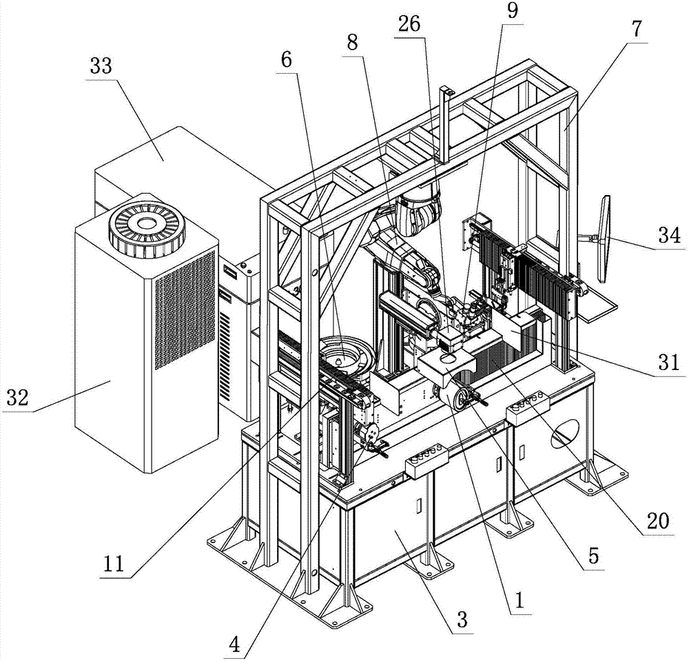
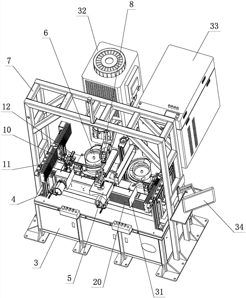
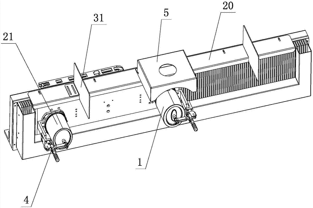
[0032] see Figure 1-Figure 11 , the pot body laser marking welding machine, including the processing pot body 1, buckle ear 2 and workbench 3, the workbench 3 is provided with at least two welding stations 4 for welding the processing pot body 1 and buckle ear 2 , and at least one marking station 5 for marking on the surface of the processing pot body 1, at least one marking station 5 is located above at least two welding stations 4, and at least two welding stations 4 are respectively A vibrating plate 6 is provided on which the buckle ear 2 is placed, and the processing pot body 1 is placed on the welding station 4; a robot hanger 7 is also arranged on the workbench 3, and a robot 8 is arranged on the robot hanger 7, The robot 8 is provided with a welding gun clamp 9, and the robot 8 moves back and forth on at least two welding stations 4 through th...


PUM


Abstract

A laser marking and welding machine of jug bodies comprises the processing jug bodies, buckled lugs and a work table. At least two welding stations and at least one marking station are arranged on the work table, wherein the welding stations are used for welding the buckled lugs to the processing jug bodies respectively, the marking stations are used for printing marks on the surfaces of the processing jug bodies, and the marking stations are located above the welding stations. Vibration plates are arranged on the welding stations respectively, the buckled lugs are arranged on the vibration plates respectively, and the processing jug bodies are arranged on the welding stations respectively; the work table is further provided with a robot hanging rack, a robot is arranged on the robot hanging rack, a welding gun clamp is arranged on the robot, the robot moves on the welding stations backwards and forwards through the robot hanging rack, and each buckled lug is welded to the corresponding processing jug body through the welding gun clamp. The laser marking and welding machine has the advantages of being simple and reasonable in structure, excellent in performance, convenient to operate, low in manufacturing cost, easy to produce, easy to implement, fully automatic, intelligent, high in production efficiency, safe, reliable and the like, and the practicability is high.

Description

technical field [0001] The invention relates to a kettle body laser marking welding machine. Background technique [0002] At present, when the existing insulation pot body and buckle ear are welded, the insulation pot body is first put on the laser marking machine to remove the paint, and then the ear buckle is placed on the insulation pot body for fixed welding. The traditional technology can only rely on manual marking. Marking and welding, however, because the whole process is done manually, and the welding laser is harmful to human eyes, the processing technology has certain safety hazards. In addition, the stability of manual processing is poor, and it is easy to make mistakes. The quality of the processed finished products is poor and inconsistent, while the processing efficiency is slow, and the processing environment for workers is harsh, which cannot meet the production and processing needs. Therefore, further improvement is necessary. Contents of the invention ...

Claims


Application Information

Patent Timeline
Patent Type & Authority Applications(China)
IPC IPC(8): B23K26/21B23K26/362B23K26/70B23K26/14
CPCB23K26/14B23K26/21B23K26/361B23K26/702Y02P70/10
Inventor 周贝贝曾磊周全
Owner GUANGDONG LXD ROBOTICS CO LTD
Learn More