Ship engine material frame

A technology for marine engines and material racks, which is applied in the direction of assembling machines, containers of machines, containers, etc., can solve the problems of large improvement projects, large hidden dangers of driving safety, and easy shaking of columns.

Active Publication Date: 2017-11-24
QINGDAO COWIN LOGISTICS EQUIP
View PDF11 Cites 5 Cited by
  • Summary
  • Abstract
  • Description
  • Claims
  • Application Information

AI Technical Summary

Problems solved by technology

[0003] Most of the existing engine turnover racks position the engine through positioning grooves and positioning blocks, and then lock and fix the engine through some briquetting blocks or bolts; most of the existing engine racks are based on the general shape ( Overall rectangle) design, and one material rack corresponds to one engine model; this results in a waste of idle material racks corresponding to the engine material after transporting one engine
Since the engine is updated very quickly, when installing the marine engine, many restrictions are used, and it is difficult to hoist into place. The existing turnover frame has been greatly changed, and there are many models of marine engines, including corners with 90° If the shape of the engine is improv

Method used


Image

  • Ship engine material frame
  • Ship engine material frame
  • Ship engine material frame

Examples


Embodiment Construction

[0022] The present invention will be described in further detail below in conjunction with specific embodiments and accompanying drawings.

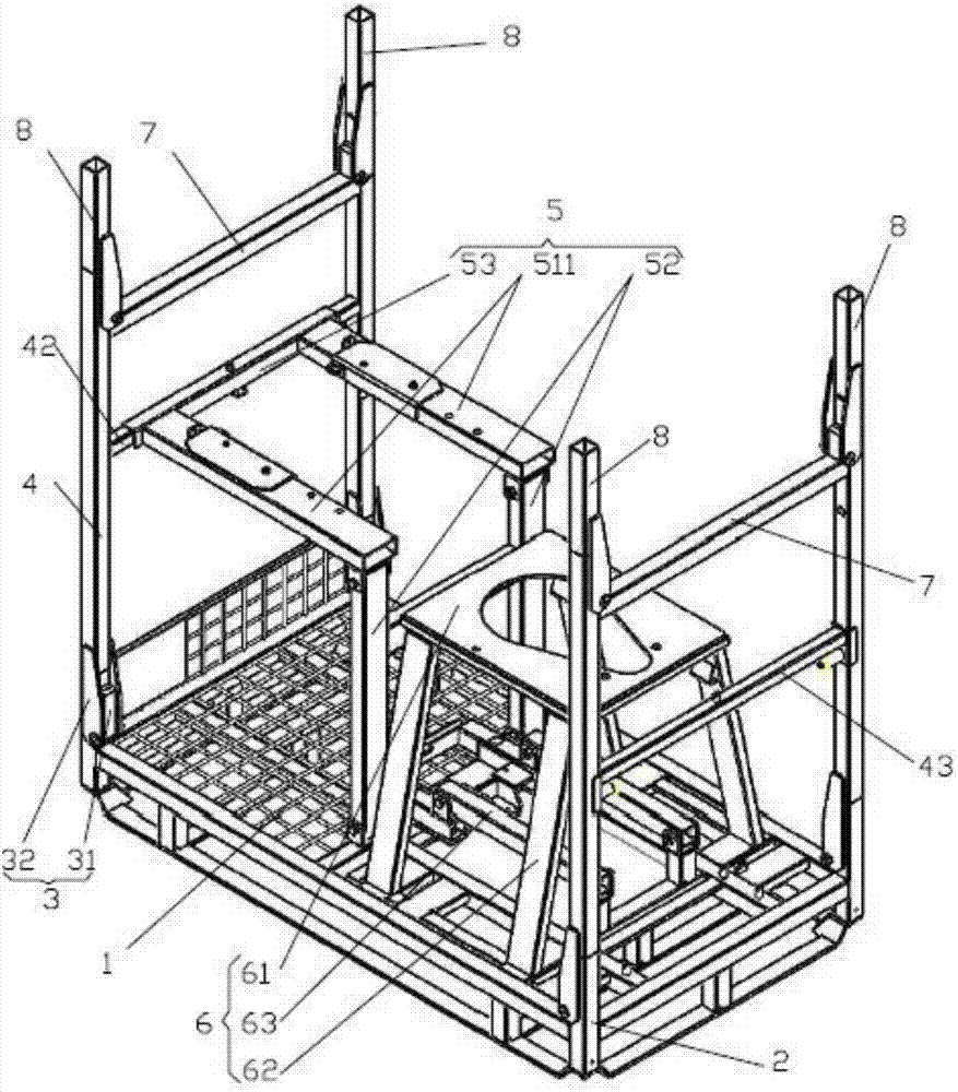
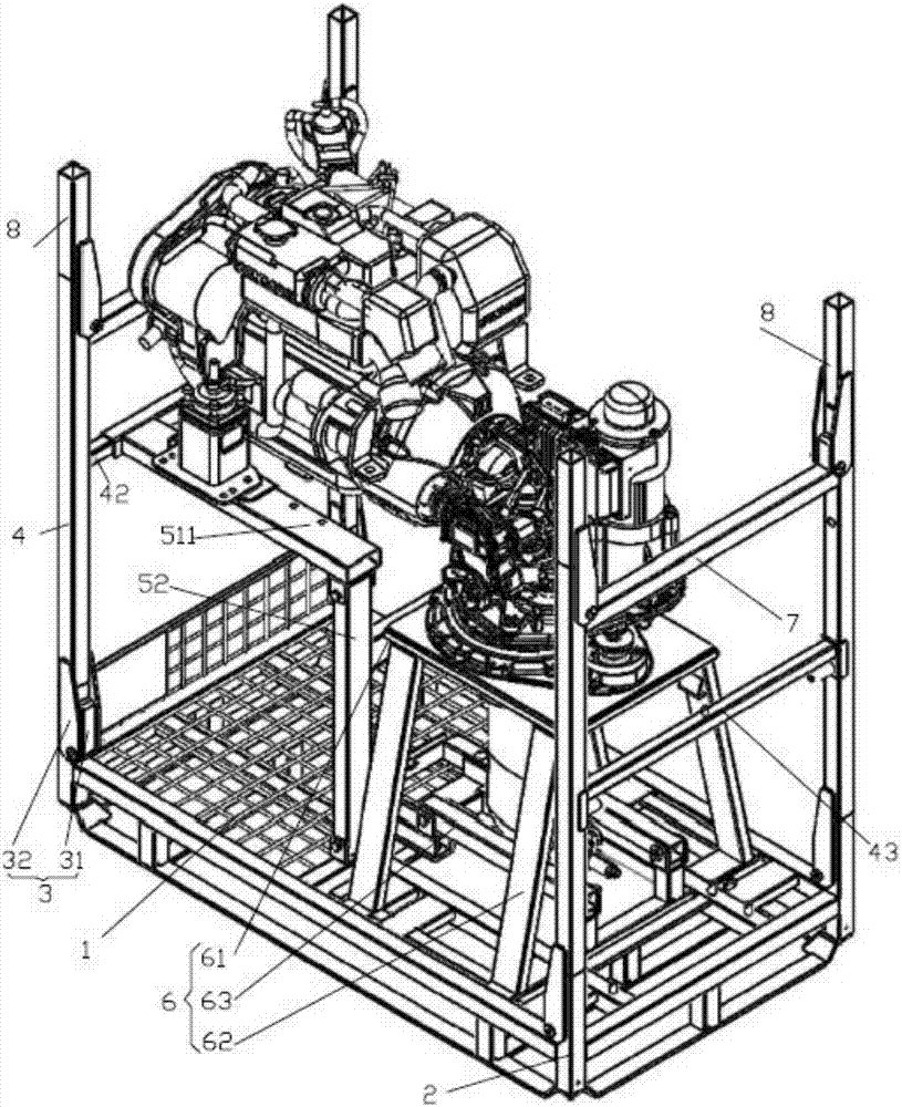
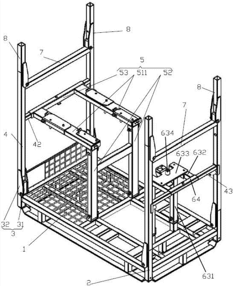
[0023] A marine engine material rack, the four corners of the bottom bracket are provided with corner posts, the top of the corner posts has a tenon, and the upper end of the corner post is rotatably connected to a movable post through a connecting mechanism; the bottom of the movable post has a tenon that matches the tenon ; There is a crossbeam between two adjacent movable columns, and a slide bar is arranged between the movable columns opposite to the crossbeam; a foldable first folding frame is arranged on the bottom support, and a second folding frame is arranged opposite to the first folding frame. frame; the first folding frame includes a mounting surface, a pillar, and a first set of rods; the mounting surface is composed of two parallel first beams, one end of the mounting surface is hinged to the pillar through a pin, and the oth...


PUM


Abstract

The invention relates to a ship engine material frame. The four corners of a bottom support are provided with corner columns, and movable columns are rotationally connected to the upper ends of the corner columns through connection mechanisms; a transverse beam is arranged between every two adjacent movable columns, and a slide rod is arranged between the other two movable columns opposite to the transverse beam; a first folding frame capable of being folded is arranged on the bottom support, and a second folding frame is arranged opposite to the first folding frame; the first folding frame comprises installing faces, supporting columns and a first loop bar; the installation faces are composed of two parallel first beams, one ends of the installing faces are hinged to the supporting columns through pin shafts, the other ends of the installing faces are fixed to the first loop bar, the supporting columns are installed on the bottom support through pin shafts, and the first loop bar buckles the transverse beam and is locked through positioning pins; and the second folding frame comprises a second installing face, the second installing face is a panel of which the middle is provided with a hole, the four corners of the panel are provided with supporting rods, the bottoms of the supporting rods are provided with a framework, and the supporting rods are movably connected to the bottom support through the framework. The ship engine material frame can be quickly positioned after hoisting and loading, the accuracy is good, and the truck loading efficiency is improved; in addition, the folding frames can be folded for storage, the folding process is easy and fast to operate and can be completed through one person, and the space for the return stroke is saved; and return stroke piling is reliable, and the running safety is improved.

Description

technical field [0001] The invention relates to an engine transport packaging device, in particular to a material rack for logistics transport of a marine engine. Background technique [0002] The engine material rack is used to fully fix the engine during the logistics transportation of the engine to ensure its safety during transmission or transportation. [0003] Most of the existing engine turnover racks position the engine through positioning grooves and positioning blocks, and then lock and fix the engine through some briquetting blocks or bolts; most of the existing engine racks are based on the general shape ( Overall rectangle) design, and one material rack corresponds to one engine model; this results in a waste of idle material racks corresponding to the engine material after transporting one engine. Since the engine is updated very quickly, when installing the marine engine, many restrictions are used, and it is difficult to hoist into place. The existing turnov...

Claims


Application Information

Patent Timeline
IPC IPC(8): B65D6/08B65D6/16B65D25/10B65D85/68
CPCB65D7/14B65D7/24B65D25/10B65D85/68
Inventor 房德琛
Owner QINGDAO COWIN LOGISTICS EQUIP
Why Eureka
Try Eureka