
Flyover structure with grooved reinforced concrete beam

A technology for reinforced concrete beams and flyover bridges, which is applied in bridges, bridge parts, bridge construction, etc., and can solve problems such as the need to expand lines, increase investment, land use, operating costs, and uninterrupted operations, so as to reduce construction difficulty and reduce construction costs. The effect of reducing and increasing degrees of freedom

Inactive Publication Date: 2017-11-24
CHINA RAILWAY DESIGN GRP CO LTD
View PDF8 Cites 0 Cited by
  • Summary
  • Abstract
  • Description
  • Claims
  • Application Information

AI Technical Summary

Problems solved by technology

Bridge crossing is required for the separation of interchanges, but under normal circumstances, the operation of existing lines that are crossed cannot be interrupted.
[0003] When designing railway and highway overpass bridges, we often encounter things that cross existing lines. We always have to consider how many degrees the intersection angle of the two lines cannot be less than, and the girder height cannot be less than how many meters. According to this requirement, some schemes cannot be implemented. Either the line needs to be extended, so investment, land use, and operating costs are increased

Method used


Image

  • Flyover structure with grooved reinforced concrete beam
  • Flyover structure with grooved reinforced concrete beam
  • Flyover structure with grooved reinforced concrete beam

Examples


Embodiment Construction

[0024] The present invention will be further described below in conjunction with the accompanying drawings.

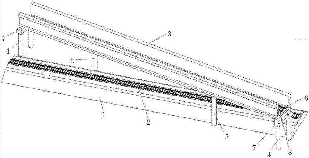
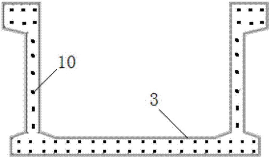
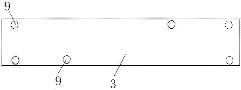
[0025] Such as Figure 1 to Figure 3 As shown, a trough-shaped reinforced concrete beam span bridge structure of the present invention includes a lower track bed 1 arranged on the ground, and the lower track bed 1 is laid with a spanned railway 2, and the ground on both sides of the lower track bed 1 Double-column piers 4 are arranged on the top, and channel beams 3 are arranged between the double-column piers 4 , and upper track bed 8 and cross-line track 6 are laid in the grooves of the channel beams 3 . The channel beam 3 is located at the upper end of the spanned railway 2, the channel beam 3 crosses the spanned railway 2 in an X shape, and the intersection angle between the centerline of the channel beam 3 and the centerline of the spanned railway 2 is less than 90°. The lower surface of the middle section of the channel beam 3 is provided with single-column pier...


PUM


Abstract

The invention discloses a flyover structure with a grooved reinforced concrete beam. The structure comprises a lower ballast bed, a crossed railway is arranged on the lower ballast bed, two-columned piers are arranged on the two sides of the lower ballast bed respectively, a grooved beam is arranged among the two-columned piers, an upper bed and a crossover line track are laid on the grooved beam, the grooved beam is located at the upper end of the crossed railway, the grooved beam and the crossed railway are crossed to form an X shape, and single-columned piers are arranged on the bottom, close to the edges of the two sides of the grooved beam, of the grooved beam respectively, wherein the single-columned piers are located on the two sides of the lower ballast bed respectively. According to the structure, existing railway operation is not affected, the height from the bottom of the ballast bed to the bottom of the grooved beam is reduced, through oblique distribution of the piers, the span is reduced, so that calculating of the beam depth is reduced, and many excellent organization solutions of station yards and lines which are impossible become possible; the structure is suitable for fields such as railways, subways, highways and water ways.

Description

technical field [0001] The invention relates to a bridge used for crossing between railways, and more specifically relates to a channel-shaped reinforced concrete beam span bridge structure. Background technique [0002] Most of the newly-built railways need to be connected with the existing lines (built-up railways), and those with large traffic volumes need to be separated by overpasses. In addition, with the increase in traffic volume and the need for safe transportation, in order to tap the potential of the railway and increase the traffic volume, many existing lines that have been decommissioned on the plane will also be changed to decommissioned. Bridge crossing is required for interchange relief, but under normal circumstances, the existing line operation of the crossed cannot be interrupted. [0003] When designing railway and highway overpass bridges, we often encounter things that cross existing lines. We always have to consider how many degrees the intersection a...

Claims


Application Information

Patent Timeline
Patent Type & Authority Applications(China)
IPC IPC(8): E01D2/00E01D19/00
CPCE01D2/00E01D19/00
Inventor 孙继忠韩金辉李怀鉴张建芳刘乃宗杨其振王建双
Owner CHINA RAILWAY DESIGN GRP CO LTD
Learn More