Lead screw drive gear meshing clutch with self-locking function

A technology of transmission teeth and clutches, applied in the field of clutches, can solve the problems of being unsuitable for space robots, and the electromagnetic clutch has a small carrying capacity, and achieves the effect of simplifying the design of the mechanism, reducing the mass, and having a large load capacity.

Active Publication Date: 2019-02-12
BEIJING INST OF SPACECRAFT SYST ENG
View PDF7 Cites 0 Cited by
  • Summary
  • Abstract
  • Description
  • Claims
  • Application Information

AI Technical Summary

Problems solved by technology

Pneumatic and hydraulic clutches are not suitable for use on space robots due to the need for air pressure and hydraulic sources during use, and the carrying capacity of electromagnetic clutches is smaller than that of mechanical clutches.

Method used


Image

  • Lead screw drive gear meshing clutch with self-locking function

Examples


Embodiment 1

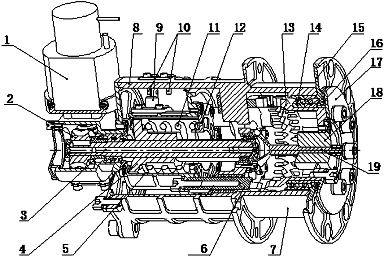
[0016] See attached figure 1 , a screw-driven gear meshing clutch with self-locking function, which includes: a motor 1, a housing 8, a ball screw 3 installed in the housing 8, fixed teeth 6 and movable teeth 13. Wherein the fixed tooth 6 is an external gear, and the movable tooth 13 is an internal gear.

[0017] The output shaft of the motor 1 is connected to the ball screw 3 through the worm gear 2, and the ball screw 3 is provided with a screw nut 4, and the screw nut 4 is sleeved with a compression spring 11 pre-tightened by a compression spring end cover 12, and the compression spring One end of 11 is in conflict with the shoulder of the lead screw nut 4, and the other end is in conflict with the fixed tooth bracket 5, so that the fixed tooth bracket 5 and the lead screw nut 4 are flexibly connected through the compression spring 11, and the fixed tooth 6 and the fixed tooth bracket 5 fixed connections.

[0018] The movable tooth 13 is installed in the housing 8 through...

Embodiment 2

[0022] The resolver shaft 19 is added on the basis of the above-mentioned embodiment 1, specifically: the resolver shaft 19 is installed in the housing 8, and a resolver for measuring the rotation angle of the movable tooth 13 relative to the housing 8 is installed on the resolver shaft 19 device 18; when the fixed teeth 6 and the movable teeth 13 are disconnected and not meshed, the movable teeth 13 can rotate freely inside the housing 8; the rotation angle of the movable teeth 13 relative to the housing 8 is measured by the resolver 19.

Embodiment 3

[0024] Furthermore, the fixed tooth bracket 5 is provided with a limit switch plate 9, and the inner circumferential surface of the housing 8 is provided with a limit switch column 10 in the direction of motion of the fixed tooth bracket 5; movement, when the fixed teeth 6 and the movable teeth 13 are fully meshed, the limit switch piece 9 contacts the right column of the limit switch column 10, and a limit signal is generated, which indicates that the clutch has been fully engaged. Motor 1 is de-energized. During the separation process of the clutch, the fixed tooth bracket 5 moves to the left. When the fixed tooth 6 and the movable tooth 13 are completely disconnected and the fixed tooth bracket 5 continues to run to the left for a certain distance, the limit switch plate 9 and the limit switch column 10 The left column contact of the left side generates a limit signal, which indicates that the clutch has been completely disengaged, and the motor 1 is de-energized at this ti...


PUM


Abstract

The invention relates to a clutch, in particular to a mechanical clutch suitable for space robots. According to the technical scheme, a lead screw transmission tooth meshed type clutch with the self-locking function comprises a motor, a shell, a ball screw installed in the shell, fixed teeth and movable teeth; the motor is a power input source, output of the motor is decelerated by a worm and gear to drive the ball screw to rotate, a lead screw nut moves in the axis direction of the ball screw, a fixed tooth support is pushed by a compressed spring to transversely move, the fixed tooth support drives the fixed teeth to transversely move in the shell, and the fixed teeth and the movable teeth are meshed or disconnected to achieve clutching of two parts. According to the lead screw transmission tooth meshed type clutch, the worm and gear are used for driving, on one hand, the deceleration function of the worm and gear is used, on the other hand, the self-locking function of the worm and gear is used, and the power-down brake function of the clutch is achieved; compared with the design combining a motor, a brake and a reducer, the mechanism design is simplified, and the mass is reduced; and compared with an electromagnetic clutch and the like, the beneficial effect of being large in load capacity is achieved.

Description

technical field [0001] The invention relates to a clutch, in particular to a mechanical clutch suitable for a space robot. Background technique [0002] A clutch is a device that can achieve the function of engaging or disengaging when the main and driven parts transmit motion and power on the axis through various manipulation methods. The clutch is similar to a switch, which is used to control the transmission of force or torque between the driving unit and the driven unit, and can realize the connection or disconnection between the driving unit and the driven unit as required. Clutches have various uses. According to the working requirements between the prime mover and the working machine or between various parts of the machine, the clutch can realize relative starting or stopping. According to the working principle of clutch engagement element transmission, it can be divided into chimeric clutch and friction clutch. According to the clutch operation mode, it can be divid...

Claims


Application Information

Patent Timeline
Patent Type & Authority Patents(China)
IPC IPC(8): F16D11/04
CPCF16D11/04
Inventor 赵志军王爽袁宝峰李德伦刘雅芳唐玲李占芯林云成冀巍高玮
Owner BEIJING INST OF SPACECRAFT SYST ENG
Why Eureka
Try Eureka