
Furnace tube turbulent flow structure and heating furnace with same

A furnace tube and spoiler technology, applied in the furnace tube spoiler structure and the heating furnace with it, can solve the problems of poor heat exchange effect, slow air flow, no flow, etc., to prolong the service life and eliminate stagnation Area, improve the effect of heat exchange energy efficiency

Pending Publication Date: 2017-11-24
THE CHALLENGE PETROCHEM MACHINERY CORP
View PDF4 Cites 0 Cited by
  • Summary
  • Abstract
  • Description
  • Claims
  • Application Information

AI Technical Summary

Problems solved by technology

The reason why the heat exchange effect on the back of the furnace tube is the worst is that there is a stagnation zone on the back of the furnace tube, and the air flow is slow or not flowing. The stagnation zone increases with the increase of the diameter of the furnace tube, which obviously affects the heating furnace. heating efficiency
In addition, after the furnace tube has been used for a long time, the smoke and dust deposited on the surface of the tube wall at the root of the support block, especially on the tube wall at the back of the furnace tube, also affects the heat exchange effect of the furnace tube

Method used


Image

  • Furnace tube turbulent flow structure and heating furnace with same
  • Furnace tube turbulent flow structure and heating furnace with same
  • Furnace tube turbulent flow structure and heating furnace with same

Examples


Embodiment 1

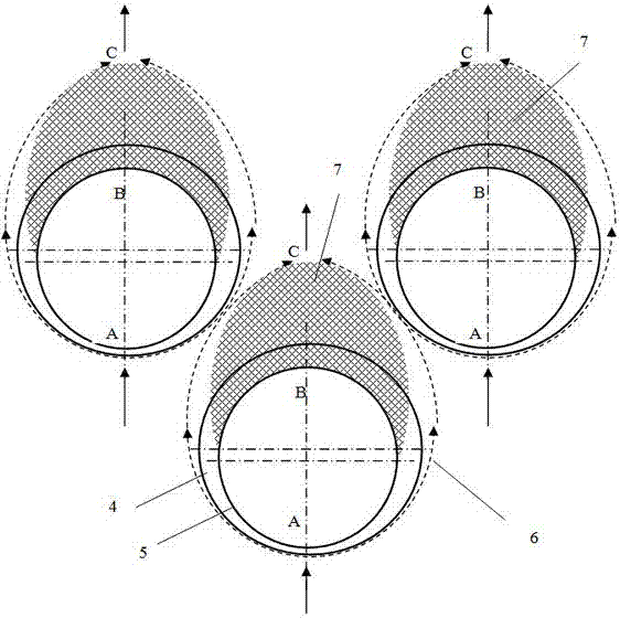
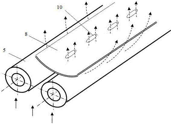
[0039] One of the specific implementations of a furnace tube turbulence structure of the present invention, such as image 3 with Figure 4 As shown, the furnace tube turbulence structure includes a spoiler 8, and the spoiler 8 is installed between two adjacent furnace tubes 5 through the legs 9, and the adjacent two furnace tubes 5 are preferably arranged in parallel, and the legs 9 and The furnace tube 5 can be cast or processed in one piece, or the legs can be assembled and welded to the outer wall of the furnace tube 5 one by one. Since each furnace tube 5 is generally installed in the corresponding tube plate hole 4, the spoiler 8 is actually installed between two adjacent tube plate holes 4. 4 is simplified or directly omitted without being shown. For the convenience of describing the core technology, the description of the tube plate hole 4 is directly omitted in this embodiment. The spoiler 8 is located on the back side of the furnace tube 5 facing away from the flow...

Embodiment 2

[0044] The second specific embodiment of a kind of furnace tube turbulence structure of the present invention, such as Figure 5 As shown, the main technical solution of this embodiment is the same as that of Embodiment 1, and the technical features not described in this embodiment are explained using Embodiment 1, and will not be repeated here. The difference between this embodiment and the embodiment is that The spoiler 8 on the furnace tube 5 can be spliced ​​end to end by multi-section spoiler 8 along the length direction of the furnace tube 5. There is a gap at the splicing part. Of course, the splicing part can also be lapped together without spot welding, which can meet the requirements of the spoiler. 8 and the need for coordination of thermal expansion and cold contraction displacement between the furnace tube, and it is also convenient for manufacturing.

[0045] The longitudinal section of the spoiler 8 taken along its length direction is corrugated, and the corruga...

Embodiment 3

[0047] The third specific embodiment of a furnace tube turbulence structure of the present invention, as Image 6 As shown, the main technical solution of this embodiment is the same as that of Embodiment 1, and the technical features not described in this embodiment are explained using Embodiment 1, and will not be repeated here. The difference between this embodiment and the embodiment is that The spoiler 8 is a spiral cylinder formed by spiraling long strips. Specifically, the long strips may be steel wires or thin steel strips. The gas flow at the side of the furnace tube 5 flows through the back of the furnace tube 5 after being deflected and diverted by the spoiler 8, thereby eliminating most of the stagnation area on the back of the furnace tube 5 in the prior art, so that the surrounding area of ​​the furnace tube A 360-degree uniform flow state is formed around, which can ultimately significantly improve the heat exchange efficiency of the furnace tube.


PUM


Abstract

The invention relates to a furnace tube turbulent flow structure and a heating furnace with the same. Furnace tubes comprise turbulent flow pieces installed between the furnace tubes, high temperature air flow is baffled and guided through the turbulent flow pieces and can flow through the back faces, back to the air flow flowing direction, of the furnace tubes, and therefore the uniform flow aim can be achieved, the high temperature air flow can flow through the back faces of the furnace tubes and generate turbulent flow, accordingly most viscous flow zones on the back faces of the furnace tubes in the prior art can be eliminated, and the aim of improving the heat exchange energy efficiency is achieved; in addition, the air flow flows through the back faces of the furnace tubes, smoke deposited to the outer walls of the back faces of the furnace tubes can be blown, and the heat exchange energy efficiency can be further improved; and in addition, the turbulent flow pieces are arranged on support blocks and achieve the strengthening and protecting effect on the support blocks, and therefore the service life of the furnace tubes is further prolonged. According to the heating furnace with the above furnace tubes, the heat exchange energy efficiency of the heating furnace can be improved, and the service life of the heating furnace can be effectively prolonged.

Description

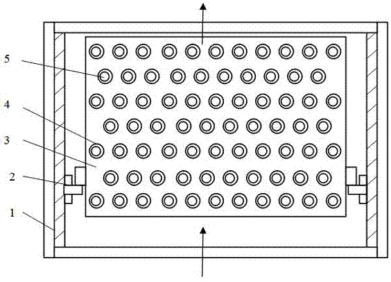
technical field [0001] The invention relates to the technical field of heating furnaces, in particular to a furnace tube turbulence structure and a heating furnace having the same. Background technique [0002] Heating furnace is the leader in petrochemical industry, usually including atmospheric pressure furnace, vacuum furnace, hydrogen production furnace, reforming furnace, coking furnace, reforming furnace and cracking furnace, etc. The function of the tube heating furnace is to heat the medium (oil or gas) to the temperature required by the process. [0003] The four sides of the furnace body of the heating furnace are surrounded by tall furnace walls. The furnace wall is made of I-steel and other steel frames covered with welded steel plates. Welded insulation nails are distributed on the steel plates, and heat insulation and wear resistance are cast between the insulation nails. Material. figure 1 It is a cross-sectional schematic diagram of a heat exchange module t...

Claims


Application Information

Patent Timeline
Patent Type & Authority Applications(China)
IPC IPC(8): F27D17/00F27B17/00
CPCF27B17/00F27D17/004
Inventor 陈孙艺
Owner THE CHALLENGE PETROCHEM MACHINERY CORP
Learn More