
Baffle assemblies and shell and tube heat exchangers incorporating same

A technology of baffles and components, which is applied in the field of enhanced heat transfer of heat exchangers, and can solve problems such as heat transfer efficiency in stagnant flow areas

Active Publication Date: 2020-02-07
NANJING NORMAL UNIVERSITY
View PDF9 Cites 0 Cited by
  • Summary
  • Abstract
  • Description
  • Claims
  • Application Information

AI Technical Summary

Problems solved by technology

[0007] In order to solve the above problems and overcome the problems that the shell-side fluid in the baffle shell-and-tube heat exchanger in the prior art is prone to flow stagnation and low heat exchange efficiency when flowing, the present invention designs a jet flow tube The baffle in the installation hole is equipped with a jet tube directly opposite the heat transfer tube, which effectively eliminates the flow stagnation area behind the baffle, and enables the heat transfer tube in the flow stagnation area to play a role in the fluid on the tube side and the shell. The effect of heat transfer between the side fluids increases the effective heat transfer area of ​​the heat exchanger and improves the heat transfer efficiency

Method used


Image

  • Baffle assemblies and shell and tube heat exchangers incorporating same
  • Baffle assemblies and shell and tube heat exchangers incorporating same
  • Baffle assemblies and shell and tube heat exchangers incorporating same

Examples


Embodiment 1

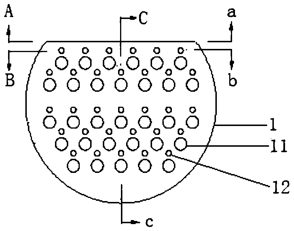
[0043] Such as image 3 As shown, a baffle assembly includes a baffle 1, and a plurality of heat transfer tube installation holes 11 are arranged in the baffle 1 for installing the heat transfer tube 2, and the feature is that: the baffle 1 is also provided with There are a plurality of jet tube installation holes 12, the jet tube 3 penetrates and is fixed in the jet tube installation hole 12, the jet tube installation hole 12 is adjacent to the heat transfer tube installation hole 11, the jet tube 3 is adjacent to the heat transfer tube 2, The jet tube 3 is provided with a jet outlet in a direction relative to the heat transfer tube 2 .

[0044] Such as Figure 5 As shown, the jet tube 3 is composed of an inlet section 31 , an installation section 32 and a jet section 33 , which are sequentially sealed and connected.

[0045] The inlet section 31 has a trumpet-shaped structure, the installation section 32 is socketed and connected with the jet tube installation hole 12, and...

Embodiment 2

[0064] Such as image 3 As shown, a baffle assembly includes a baffle 1, and a plurality of heat transfer tube installation holes 11 are arranged in the baffle 1 for installing the heat transfer tube 2, and the feature is that: the baffle 1 is also provided with There are a plurality of jet tube installation holes 12, the jet tube 3 penetrates and is fixed in the jet tube installation hole 12, the jet tube installation hole 12 is adjacent to the heat transfer tube installation hole 11, the jet tube 3 is adjacent to the heat transfer tube 2, The jet tube 3 is provided with a jet outlet in a direction relative to the heat transfer tube 2 .

[0065] Such as Figure 5 As shown, the jet tube 3 is composed of an inlet section 31 , an installation section 32 and a jet section 33 , which are sequentially sealed and connected.

[0066] The inlet section 31 has a trumpet-shaped structure, the installation section 32 is socketed and connected with the jet tube installation hole 12, and...

Embodiment 3

[0080] Such as Figure 4 As shown, a baffle assembly includes a baffle 1, and a plurality of heat transfer tube installation holes 11 are arranged in the baffle 1 for installing the heat transfer tube 2, and the feature is that: the baffle 1 is also provided with There are a plurality of jet tube installation holes 12, the jet tube 3 penetrates and is fixed in the jet tube installation hole 12, the jet tube installation hole 12 is adjacent to the heat transfer tube installation hole 11, the jet tube 3 is adjacent to the heat transfer tube 2, The jet tube 3 is provided with a jet outlet in a direction relative to the heat transfer tube 2 .

[0081] Such as Figure 5 As shown, the jet tube 3 is composed of an inlet section 31 , an installation section 32 and a jet section 33 , which are sequentially sealed and connected.

[0082] The inlet section 31 has a trumpet-shaped structure, the installation section 32 is socketed and connected with the jet tube installation hole 12, an...


PUM


Abstract

The invention relates to a baffle assembly. The baffle assembly comprises an arch-shaped baffle, and a plurality of heat transfer tube mounting holes are formed in the arch-shaped baffle and used forinstalling heat transfer tubes; a plurality of jet flow tube mounting holes are further formed in the arch-shaped baffle, jet flow tubes penetrate through and are fixed in the jet flow tube mounting holes, and the jet flow tube mounting holes are close to the heat transfer tube mounting holes; the jet flow tubes are close to the heat transfer tubes. Each jet flow tube is composed of an inlet section, a mounting section and a jet section, wherein the inlet section is of a horn-shaped structure, the tail end of the jet section is of a closed structure, and a jet flow outlet is formed in the portion, right opposite to the corresponding heat transfer tube, of the jet flow section. By means of the baffle assembly, a flow stagnation area behind the baffle can be effectively eliminated, and the heat transfer tubes of the flow stagnation area can play a role in transferring heat between a tube side fluid and a shell side fluid, so that the effective heat transfer area of the heat exchanger isincreased, and the heat exchange efficiency is improved.

Description

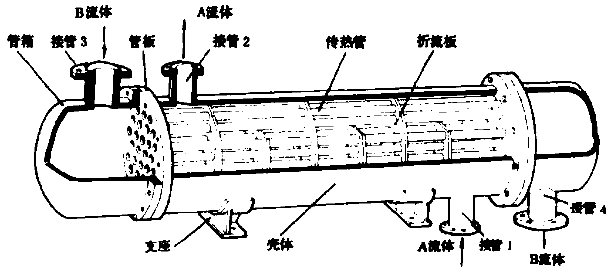
technical field [0001] The invention belongs to the technical field of enhanced heat transfer of heat exchangers, and in particular relates to a baffle assembly and a shell-and-tube heat exchanger including the assembly. Background technique [0002] figure 1 It is a simplified structural diagram of a shell-and-tube heat exchanger in the prior art, in which fluid A flows outside the heat transfer tube and is called the shell-side fluid, fluid B flows inside the heat transfer tube and is called the tube-side fluid, and fluid A and B flow The temperature is different, and the heat exchange between them is realized through the heat transfer tube. In order to increase heat transfer, both the tube side fluid and the shell side fluid should have high convective heat transfer coefficients. According to the principle of heat transfer, the convective heat transfer coefficient of the tube-side fluid in the tube is very large, while the shell-side fluid outside the tube must take cer...

Claims


Application Information

Patent Timeline
Patent Type & Authority Patents(China)
IPC IPC(8): F28D7/16F28F9/22F28F9/24
CPCF28D7/1638F28F9/22F28F9/24F28F2009/224
Inventor 张奕李奇贺
Owner NANJING NORMAL UNIVERSITY
Learn More