
Studded tube with uniform flow cover and heating furnace with studded tube

A nail head and flow cover technology is applied in the field of heating furnace, which can solve the problems of poor heat exchange effect, slow airflow, affecting the heat exchange effect of nail head tube, etc., and achieve the effect of improving heat exchange energy efficiency and prolonging service life.

Pending Publication Date: 2018-02-16
THE CHALLENGE PETROCHEM MACHINERY CORP
View PDF6 Cites 0 Cited by
  • Summary
  • Abstract
  • Description
  • Claims
  • Application Information

AI Technical Summary

Problems solved by technology

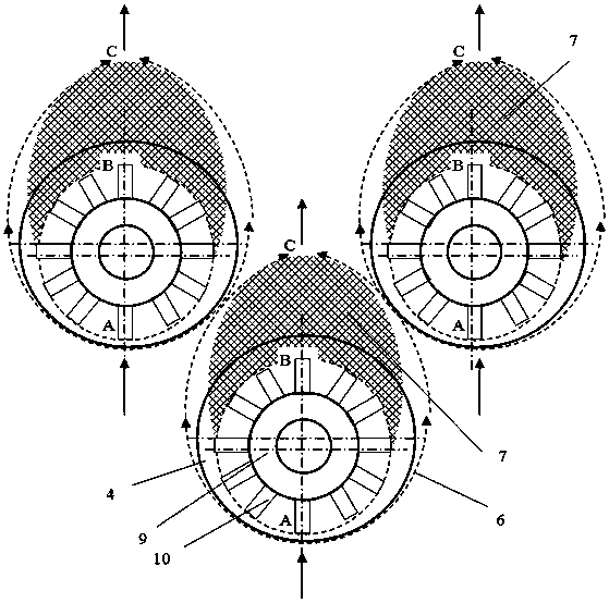
The reason why the heat transfer effect on the leeward side of the nailhead tube is the worst is that there is a stagnation zone on the leeward side of the nailhead tube, where the air flow is slow or not, and the stagnation area increases with the increase of the diameter of the nailhead tube , significantly affect the heating efficiency of the furnace
In addition, after the nail head tube is used for a long time, the smoke and dust deposited on the surface of the tube wall at the root of the nail head, especially on the tube wall on the leeward side of the nail head tube, also affects the heat transfer effect of the nail head tube

Method used


Image

  • Studded tube with uniform flow cover and heating furnace with studded tube
  • Studded tube with uniform flow cover and heating furnace with studded tube
  • Studded tube with uniform flow cover and heating furnace with studded tube

Examples


Embodiment 1

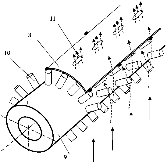
[0039] One of the specific implementations of a nail head tube with a uniform flow cover of the present invention, such as image 3 and Figure 4 As shown, the nail head tube includes a base pipe 9 and a nail head 10 installed on the outer wall of the base pipe 9 for accelerating heat exchange. Group welded to the outer wall of the base pipe 9. The nail head 10 located on the back side of the base pipe 9 facing away from the flow direction of the air flow is provided with a uniform flow cover 8, the cross section of the nail head 10 is circular, oblong or rectangular, and the root of the nail head 10 is affixed to the base pipe 9, The end of the nail head 10 is welded and fixed with the uniform flow cover 8, specifically, as image 3 The middle uniform flow cover 8 can be close to the nail head tube on the whole bottom surface, and the two sides of the uniform flow cover 8 are fixedly connected with the nail head 10 by spot welding respectively. Of course, it can also be fix...

Embodiment 2

[0044] The second specific embodiment of a nailhead tube with a uniform flow cover of the present invention, as Figure 5 As shown, the main technical solution of this embodiment is the same as that of Embodiment 1, and the technical features not described in this embodiment are explained using Embodiment 1, and will not be repeated here. The difference between this embodiment and the embodiment is that The uniform flow cover 8 on the nail head 10 can be formed by splicing the multi-section uniform flow cover 8 end to end along the length direction of the base pipe 9. There is a gap at the splicing part. Of course, the splicing parts can also be overlapped together without spot welding, which can meet the requirements of the uniform flow cover. The need for thermal expansion and cold contraction coordination between the 8 and the nail head tube is also convenient for manufacturing.

[0045] In this embodiment, the uniform flow cover 8 and the nail head pipe are assembled toget...

Embodiment 3

[0047] The third specific embodiment of a nailhead tube with a uniform flow cover of the present invention, as Figure 6 As shown, the main technical solution of this embodiment is the same as that of Embodiment 1, and the technical features not described in this embodiment are explained using Embodiment 1, and will not be repeated here. The difference between this embodiment and the embodiment is that The uniform flow cover 8 and the nail head tube are clamped on the nail head tube by using elastic pins 13, which simplifies the assembly process.


PUM


Abstract

The invention relates to a studded tube with a uniform flow cover and a heating furnace with the studded tube. The studded tube comprises a base tube and studs for accelerating heat exchange; the uniform flow cover is arranged on the studs, located on the back surface, opposite to the air flow direction, of the base tube; high-temperature air can flow through stud gaps on the back surface of the base tube after being baffled and guided by the uniform flow cover, and accordingly, the purpose of uniform flow can be achieved, the high-temperature air can flow through the studs on the back surfaceof the base tube and generate turbulence, most of the stagnation area on the back surface of the base tube in the prior art can be eliminated, and the purpose of improving heat exchange energy efficiency is achieved. Moreover, the air can also purge soot deposited on the back surface of the base tube when flowing through the back surface, so that the heat exchange energy efficiency is further improved, and the service life of the studs is also prolonged. Besides, the uniform flow cover is arranged on the studs to strengthen and protect the studs, and the service life of the studded tube is further prolonged. The heating furnace with the studded tube has the advantages that the heat exchange energy efficiency of the heating furnace can be improved, and the service life of the heating furnace can also be effectively prolonged.

Description

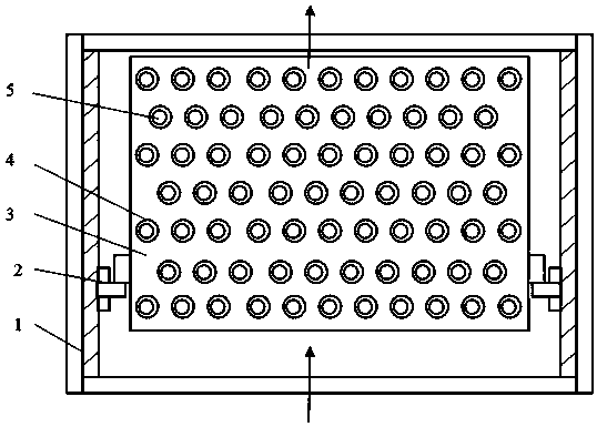
technical field [0001] The invention relates to the technical field of heating furnaces, in particular to a nail head tube with a uniform flow cover and a heating furnace with the same. Background technique [0002] Heating furnace is the leader in petrochemical industry, usually including atmospheric pressure furnace, vacuum furnace, hydrogen production furnace, reforming furnace, coking furnace, reforming furnace and cracking furnace, etc. The function of the tube heating furnace is to heat the medium (oil or gas) to the temperature required by the process. [0003] The four sides of the furnace body of the heating furnace are surrounded by tall furnace walls. The furnace wall is made of I-steel and other steel frames covered with welded steel plates. Welded insulation nails are distributed on the steel plates, and heat insulation and wear resistance are cast between the insulation nails. Material. figure 1 It is a cross-sectional schematic diagram of a heat exchange mod...

Claims


Application Information

Patent Timeline
Patent Type & Authority Applications(China)
IPC IPC(8): F28F1/12F27B17/00
CPCF27B17/00F28F1/12
Inventor 陈孙艺
Owner THE CHALLENGE PETROCHEM MACHINERY CORP
Learn More