Hall product testing mechanism and assembling and testing method

A technology for product testing and test pieces, which is applied in the direction of measuring devices, measuring magnetic variables, instruments, etc., can solve problems such as easy material stacking, left and right deviation, and insufficient stability of the magnetic field, so as to improve production efficiency, reduce lifting range, and external interference Reduced effect

Active Publication Date: 2017-11-24
CHANGJIANG ELECTRONICS TECH CHUZHOU
View PDF7 Cites 8 Cited by
  • Summary
  • Abstract
  • Description
  • Claims
  • Application Information

AI Technical Summary

Problems solved by technology

[0007] In the process of testing finished chips in the prior art, the magnetic field of the Hall coil in the test area is not stable enough, the difference between the maximum and minimum Gauss values ​​measured is very large, and the package is shifted left and right in the test clip during the package test, resulting in inaccurate positioning. Accuracy, and after the test is completed, the package is easy to stack in the test station and transferred to the sub-panel. The present invention provides a Hall product testing mechanism and an assembly and testing method.
It achieves the purpose of providing a stable magnetic field by ingeniously designing the counterbore to accommodate the Hall test piece at one end of the Hall coil, and the test clamp of the present invention can be adaptively adjusted according to the size of the package to achieve the purpose of accurate positioning , after adjusting the positioning of the package, it also solves the problem of easy stacking of materials transferred to the sub-panel after the test is completed

Method used


Image

  • Hall product testing mechanism and assembling and testing method
  • Hall product testing mechanism and assembling and testing method
  • Hall product testing mechanism and assembling and testing method

Examples


Embodiment 1

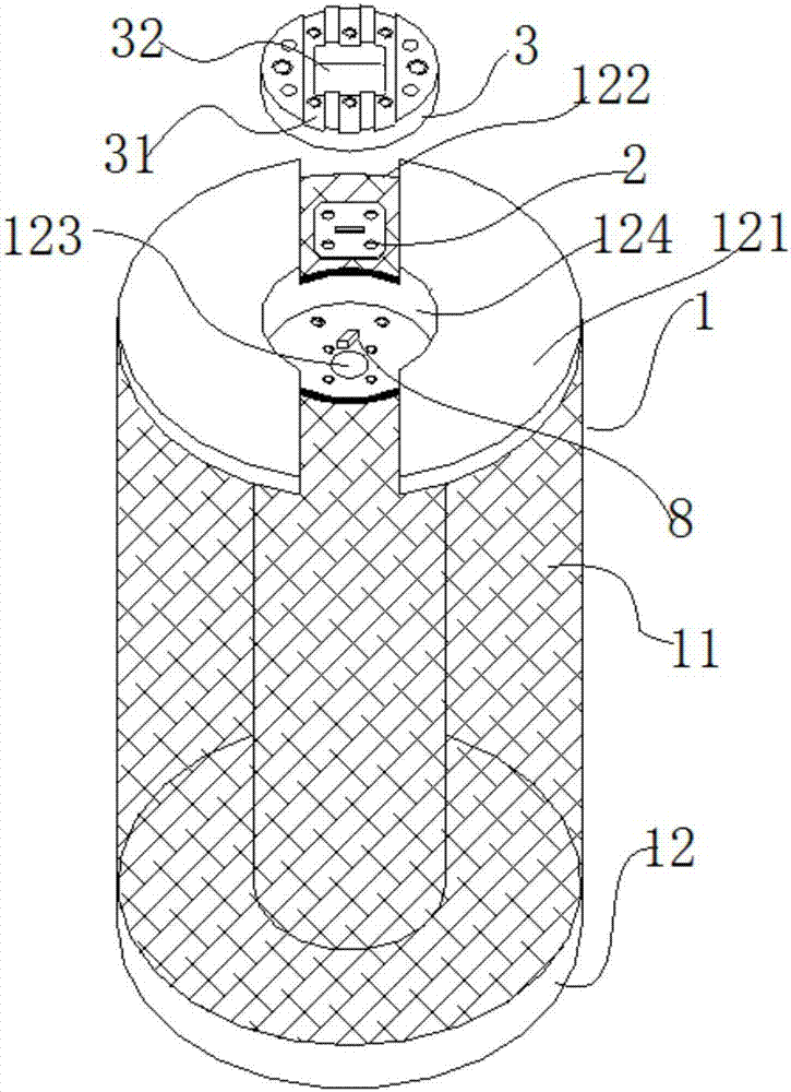
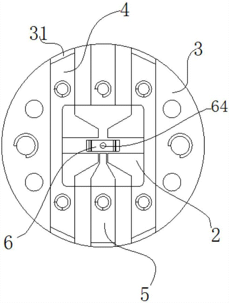
[0064] The Hall product testing mechanism of the present embodiment, such as figure 1As shown, it includes a Hall coil 1, a collar 2, a base 3, a Hall test piece and a Hall test clip; the Hall coil 1 includes an I-shaped support 12 and an enameled wire coil wrapped in the middle part of the I-shaped support 12 11. One end of the I-shaped bracket 12 is a ring platform 121, and the center of the ring platform 121 is a circular groove 124; the center of the circular groove 124 is a circular through hole 123, which can place 8 products to be tested Into the circular groove 124 for detection, during detection, the external interference received is reduced, and a stable magnetic field is provided; the base 3 is circular, embedded in the circular groove 124, and the Hall test piece fixed on the upper surface of the base 3; as Figure 4 As shown, the middle of the base 3 is a square collar positioning hole 32, and the collar 2 is embedded in the collar positioning hole 32; as Figu...

Embodiment 2

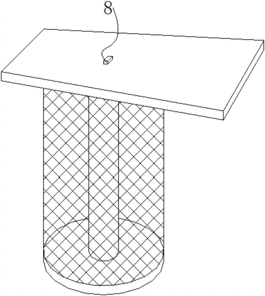
[0068] The Hall product testing mechanism of this embodiment, the basic structure is the same as that of Embodiment 1, the differences and improvements are: the Hall test clip is improved to the Hall movable clip 6; the depth of the circular groove 124 is not less than the base 3, the Hall The sum of the thicknesses of the test piece and the product to be tested 8, so as to ensure that the product to be tested 8 can not protrude from the circular groove 124, thereby ensuring the stability of the test magnetic field; Figure 15 , 16 As shown, the Hall movable clip 6 includes a fixed clip 61, a movable clip 62, a connecting rod 65 and a base 610; The rotation of the clip 61 realizes the width adjustment of the jaw 6111 between the two; the bottom of the fixed clip 61 is fixed with a connecting rod 65; just below the connecting rod 65, a base 610 with a blind hole 6101 is provided, the connecting rod 65 and The blind hole 6101 fits with the upper and lower gaps, and moves up and...

Embodiment 3

[0070] The Hall product testing mechanism of present embodiment, basic structure is the same as embodiment 2, difference and improvement are: as Figure 10 , 11 , 12, on the ring platform 121, there are two left and right symmetrical slots 122 outwards from the circular groove 124, which provide the passage for the product 8 to be tested; the rotating device is a fixed clip 61, a movable clip 62 are provided respectively on the respective side faces facing each other with a convex semi-cylinder 612 and a concave semi-cylindrical 622; The convex semi-cylinder 612 is pivoted.


PUM


Abstract

The invention belongs to the technical field of chip testing and discloses a Hall product testing mechanism and an assembling and testing method. The Hall product testing mechanism comprises a Hall movable clamp, a Hall coil, a collar, a base and a Hall test piece. The Hall coil comprises an I-shaped support and an enameled wire coil which coats the middle of the I-shaped support, one end of the I-shaped support is provided with an annular plate with a round groove in the center, and the center of the round groove is provided with a round through hole. The base is circular and embedded into the round groove, and the Hall test piece is fixed to the upper surface of the base. The middle of the collar is provided with a square hole which annularly sleeves the top end of the Hall movable clamp, and the tail end of the Hall movable clamp is inserted into the round through hole. The whole mechanism forms a positioning and fixing device of the Hall test piece and the Hall movable clamp. By the Hall product testing mechanism and the assembling and testing method, the problem of large difference between maximum and minimum values of measured Gaussian quantity due to magnetic field instability of the Hall coil in a test area in a chip testing process is solved.

Description

technical field [0001] The invention relates to the technical field of chip testing, in particular to a Hall product testing mechanism and an assembly and testing method. Background technique [0002] At present, in the semiconductor integrated circuit manufacturing process, it is necessary to further test the finished chips after cutting and packaging. During the testing process, the Hall coil plays the role of providing a magnetic field. The Hall device test fixture is a fixture used to test the finished Hall device. During the test process, the specific method is to transfer the Hall device to the test clip through the suction nozzle of the chip sorter. After the test is completed, the suction nozzle of the chip sorter will transfer the Hall device to the next process, and the packaging The pins of the body are arranged symmetrically on the left and right. How to ensure the contact between the pins on both sides and the Hall test piece during the test and how to prevent ...

Claims


Application Information

Patent Timeline
Patent Type & Authority Applications(China)
IPC IPC(8): G01R33/00
CPCG01R33/00
Inventor 李国祥李青
Owner CHANGJIANG ELECTRONICS TECH CHUZHOU
Why Eureka
Try Eureka