Omnidirectional chipless RFID tag based on angle positioning

An RFID tag and angle positioning technology, applied in the field of the Internet of Things, can solve the problems of polarization mismatch, difficult to adapt to the complex and changeable environmental requirements of the tag position, etc., and achieve the effect of changing the angle sensitivity

Active Publication Date: 2017-11-24
SOUTH CHINA UNIV OF TECH
View PDF4 Cites 4 Cited by
  • Summary
  • Abstract
  • Description
  • Claims
  • Application Information

AI Technical Summary

Problems solved by technology

However, most of the designs have the problem of polarization mismatch between the tag and the reader due to the change of the alignment angle. This defect makes the

Method used


Image

  • Omnidirectional chipless RFID tag based on angle positioning
  • Omnidirectional chipless RFID tag based on angle positioning
  • Omnidirectional chipless RFID tag based on angle positioning

Examples


Embodiment

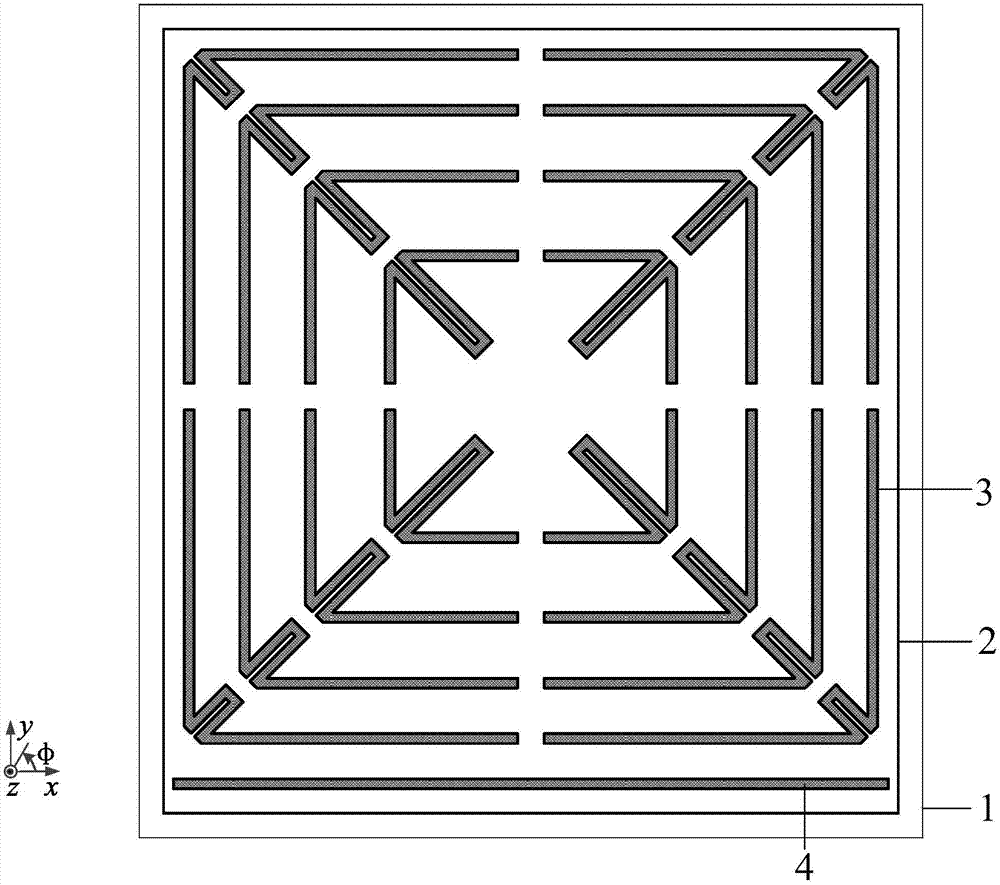
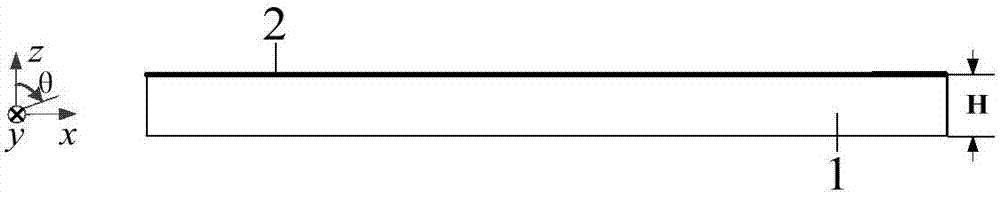
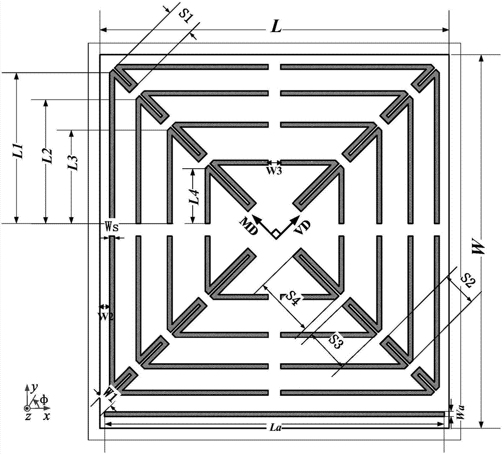
[0035] Such as figure 1 and figure 2 As shown, an omnidirectional chipless RFID tag based on angle positioning, the tag is a symmetrical structure, including an antenna radiation patch structure 2 and a dielectric substrate structure 1, and the antenna radiation patch structure is located on the dielectric substrate structure On the surface, the antenna radiation patch structure is composed of a rectangular patch, and the rectangular patch is printed with an upper coding unit 3 and a lower positioning unit 4, and the lower positioning unit is located directly below the upper coding unit.

[0036] The upper coding unit is composed of four groups of arrow-shaped slots with the same structural size, and the four groups are respectively slotted symmetrically along the main and auxiliary diagonals. Adjacent two groups of arrow-shaped grooves are separated by a certain distance, and the four groups are respectively located at the four corners of the rectangular patch, of which two...


PUM


Abstract

The invention discloses an omnidirectional chipless RFID tag based on angle positioning. The RFID tag comprises an antenna radiating patch structure and a dielectric substrate structure. The antenna radiating patch structure is located on the upper surface of the dielectric substrate structure. The antenna radiating patch structure is composed of a rectangular patch printed with an upper coding unit and a lower positioning unit, wherein the lower positioning unit is located directly below the upper coding unit. The omnidirectional chipless RFID tag provided by the invention has the advantages of omnidirectionality, miniaturization, large capacity, high spectrum utilization, easy printing and the like, and is applicable to the field of Internet of Things.

Description

technical field [0001] The invention relates to the field of the Internet of Things, in particular to an omnidirectional chipless RFID tag based on angle positioning. Background technique [0002] Radio Frequency Identification (RFID) technology has advantages over identification technologies such as bar codes and smart cards. RFID can automatically identify the tags attached to different objects, and conduct wireless communication through the electromagnetic propagation between the tags and the reader. Line of Sight) detection. However, barcodes and smart cards must be accurately placed in designated positions, and automatic identification cannot be realized. The reading distance of the barcode is also very short, and there must be no obstruction between them; smart cards require direct contact between the card and the reader. In addition, RFID readers can quickly identify multiple tags within a certain range, while barcodes and smart cards can only be read one-to-one. ...

Claims


Application Information

Patent Timeline
IPC IPC(8): G06K19/077G06K19/07
CPCG06K19/0716G06K19/07771G06K19/07773Y02D30/70
Inventor 刘雄英王泽众韦岗
Owner SOUTH CHINA UNIV OF TECH
Why Eureka
Try Eureka