Antenna adaptation method and terminal

An antenna and terminal technology, applied to antennas, antenna parts, and devices that enable antennas to work in different bands at the same time, to achieve the effects of low heat generation, improved communication signal quality, and low power consumption

Active Publication Date: 2020-10-16
VIVO MOBILE COMM CO LTD
View PDF5 Cites 0 Cited by
  • Summary
  • Abstract
  • Description
  • Claims
  • Application Information

AI Technical Summary

Problems solved by technology

[0004] The present invention provides an antenna adaptation method, antenna and terminal to solve the above-mentioned problems existing in the existing antenna application process

Method used


Image

  • Antenna adaptation method and terminal
  • Antenna adaptation method and terminal
  • Antenna adaptation method and terminal

Examples


Embodiment 1

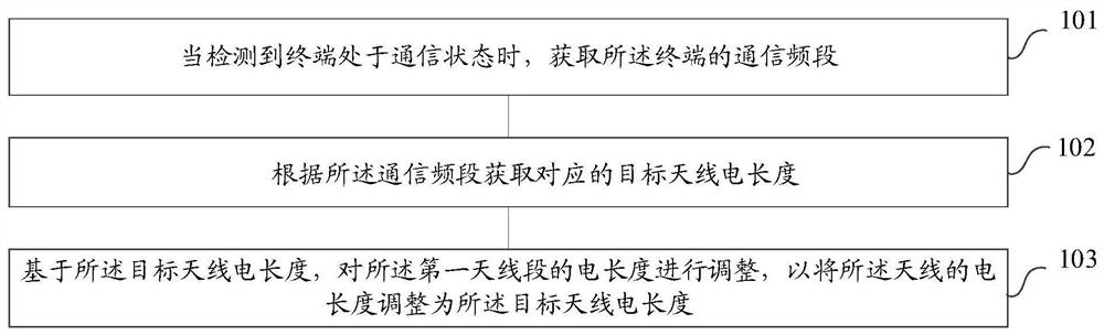
[0056] Reference figure 1 , Shows a step flow chart of an antenna adaptation method according to Embodiment 1 of the present invention. The antenna includes at least a first antenna section, and the first antenna section is made of a deformable alloy. The method of antenna adaptation may include the following steps:

[0057] Step 101: When it is detected that the terminal is in a communication state, acquire the communication frequency band of the terminal;

[0058] Step 102: Obtain the corresponding target antenna electrical length according to the communication frequency band;

[0059] Step 103: Based on the electrical length of the target antenna, adjust the electrical length of the first antenna segment to adjust the electrical length of the antenna to the electrical length of the target antenna.

[0060] In the antenna adaptation method provided by the embodiment of the present invention, when it is detected that the terminal is in a communication state, the current communication...

Embodiment 2

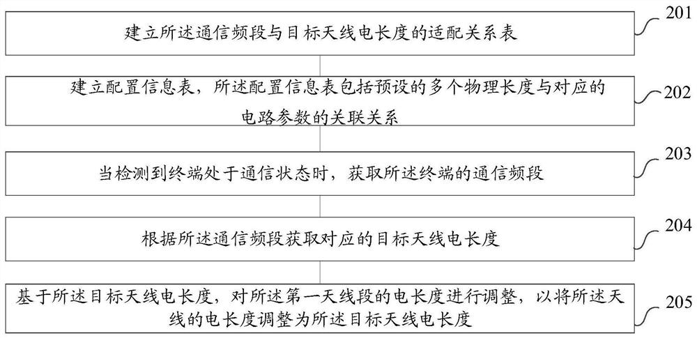
[0062] Reference figure 2 , Shows a step flow chart of an antenna adaptation method according to the second embodiment of the present invention. The antenna includes at least a first antenna section. The first antenna section is made of deformable alloy. The antenna segment is connected to the control circuit, and the control circuit has circuit parameters. The antenna adaptation method of the embodiment of the present invention may include the following steps:

[0063] Step 201: Establish an adaptation relationship table between the communication frequency band and the electrical length of the target antenna;

[0064] Specifically, the communication frequency band is used to carry the wireless spectrum resources of the business operated by the communication operator. The communication frequency bands owned by different operators are different. For example, the communication frequency band owned by China Mobile, for TD-LTE (Time Division Long Term Evolution, time-sharing long-term...

Embodiment 3

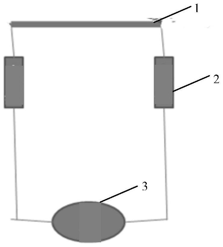
[0139] The embodiment of the present invention also discloses an antenna. The antenna includes at least a first antenna section, the first antenna section is made of deformable alloy, and the electrical length of the first antenna section is suitable for the communication frequency band of the terminal. Match.

[0140] In a preferred embodiment of the present invention, the antenna further includes a second antenna segment, and the physical length of the second antenna segment is a fixed value.

[0141] In a preferred embodiment of the present invention, the first antenna segment is connected to a control circuit, and the control circuit adjusts the physical length of the first antenna segment according to circuit parameters.

[0142] In a preferred embodiment of the present invention, the circuit parameters include voltage and / or current.

[0143] In a preferred embodiment of the present invention, an inductor is connected in series at both ends of the first antenna segment.

[0144] ...


PUM


Abstract

The present invention provides a method for adapting an antenna, an antenna and a terminal. The antenna includes at least a first antenna segment, and the first antenna segment is made of a deformable alloy. Through the method provided by the present invention, when the terminal is detected When in the communication state, the current communication frequency band of the terminal can be obtained, and the corresponding target antenna electrical length can be obtained according to the communication frequency band. Based on the target antenna electrical length, the antenna of the terminal can be set to include For the first antenna segment, the electrical length of the antenna of the terminal can be adjusted to the target antenna electrical length by adjusting the electrical length of the first antenna segment, so that the electrical length of the antenna when the terminal communicates in the current frequency band is the electrical length of the antenna with the highest antenna efficiency, greatly improving The quality of the communication signal during user communication is improved, and at the same time, the power consumption of the terminal is small, and the heat generation is small, which improves the user experience.

Description

Technical field [0001] The present invention relates to the technical field of terminals, in particular to an antenna adaptation method, antenna and terminal. Background technique [0002] With the development of the 4G era, the communication frequency bands supported by mobile phones and other terminals continue to increase, which has greatly increased the difficulty of terminal antenna design. For all communication frequency bands supported by the terminal, it is difficult to achieve high antenna efficiency, resulting in the terminal’s communication process. For some communication frequency bands, the antenna efficiency is low during communication, which leads to large power consumption of the terminal, large heat generation, and poor communication signal, which affects user experience. [0003] Currently, there is no suitable technical solution to solve the problems encountered in the current terminal communication process. Summary of the invention [0004] The present invention...

Claims


Application Information

Patent Timeline
Patent Type & Authority Patents(China)
IPC IPC(8): H01Q1/36H01Q5/307
CPCH01Q1/36H01Q1/364H01Q5/307Y02D30/70
Inventor 陈巍伟
Owner VIVO MOBILE COMM CO LTD
Why Eureka
Try Eureka