
T-shaped coupling dual-polarization base station antenna

A base station antenna and dual-polarization technology, which is applied in the field of T-shaped coupling dual-polarization base station antennas, to achieve the effects of reducing the number of solder joints, improving impedance bandwidth, and reducing passive intermodulation distortion

Pending Publication Date: 2017-11-24
CHINA TOWER CO LTD
View PDF0 Cites 2 Cited by
  • Summary
  • Abstract
  • Description
  • Claims
  • Application Information

AI Technical Summary

Problems solved by technology

However, the impedance bandwidth of this antenna is only 32%

Method used


Image

  • T-shaped coupling dual-polarization base station antenna
  • T-shaped coupling dual-polarization base station antenna
  • T-shaped coupling dual-polarization base station antenna

Examples


Embodiment Construction

[0026] The present invention will be described in detail below in conjunction with the accompanying drawings.

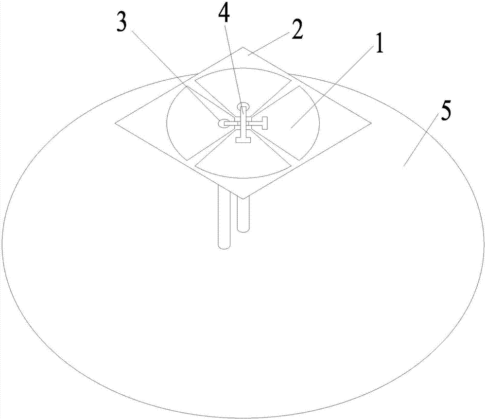
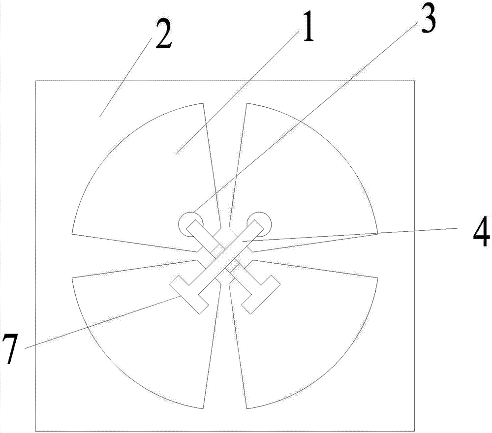
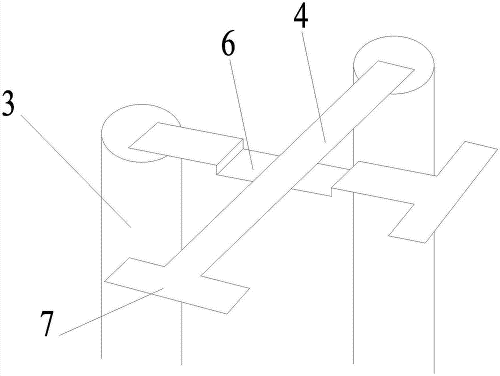
[0027] The T-shaped coupled dual-polarized base station antenna of the present invention includes: four fan-shaped radiation units 1 , a dielectric substrate 2 , two feed units 4 , two coaxial cables 3 and a circular reflector 5 .

[0028] Wherein, the reflection plate 5 under the dielectric substrate 2 can realize stable directional radiation, thereby increasing the gain of the antenna. The radiating unit 1 and the feeding unit 4 are respectively located on the upper and lower surfaces of the FR4 dielectric substrate 2 with a relative thickness of 0.8 mm. The radiation unit 1 is located on the lower surface of the dielectric substrate 2 , and the feeding unit 4 is located on the upper surface of the dielectric substrate 2 . Four radiating units 1 are arranged at intervals of 90° in the circumferential direction on the lower surface of the dielectric substrate 2; tw...


PUM

PropertyMeasurementUnit
Thicknessaaaaaaaaaa

Abstract

The invention relates to a T-shaped coupling dual-polarization base station antenna. The T-shaped coupling dual-polarization base station antenna comprises a dielectric substrate, a reflection plate and two coaxial cables, wherein four radiation units are arranged on a lower surface of the dielectric substrate in a circumferential direction at an interval of 90 degrees, two feeding units are arranged on an upper surface of the dielectric substrate in the circumferential direction at an interval of 90 degrees, each feeding unit is correspondingly arranged above the two radiation units at an interval of 180 degrees in the circumferential direction, the two feeding units are crossed at a central position of the four radiation units, the reflection plate is arranged below the dielectric substrate, lower ends of the two coaxial cables are respectively connected with the reflection plate, and upper ends of the two coaxial cables are connected with the two feeding units. The T-shaped coupling dual-polarization base station antenna employs a T-shaped feeding structure, the impedance matching of the antenna can be effectively adjusted, and the impedance bandwidth of the antenna is improved and reaches 42%.

Description

technical field [0001] The invention relates to a base station antenna, in particular to a T-shaped coupling dual-polarized base station antenna. Background technique [0002] The circuit parameters and radiation parameter performance of the antenna are often a function of the frequency, which will change with the continuous change of the frequency. The parameter index of the antenna changes within a certain frequency range, which is called the bandwidth of the antenna. Broadband and multi-frequency base station antennas have become a key research direction for scholars at home and abroad in the field of base station antennas. [0003] There is an L-shaped coupling feed structure in the prior art, and there is a gap between the horizontal part of the end and the radiation patch, and the gap exhibits a capacitive characteristic, thereby canceling the inductance of the probe itself. However, the impedance bandwidth of this antenna is only 32%. Contents of the invention [...

Claims


Application Information

Patent Timeline
IPC IPC(8): H01Q1/38H01Q1/50H01Q19/10
CPCH01Q1/38H01Q1/50H01Q19/104
Inventor 王祥宇林开季宏刘开宇
Owner CHINA TOWER CO LTD
Learn More