Al technical title is built by PatSnap Al team. It summarizes the technical point description of the patent document.
A belt and small-scale technology, applied in the field of forging machinery, can solve problems such as easy-to-break tension springs, and achieve the effects of low cost, flexible operation, and simple design
Inactive Publication Date: 2017-11-28
杨朴
View PDF6 Cites 1 Cited by
Summary
Abstract
Description
Claims
Application Information
AI Technical Summary
This helps you quickly interpret patents by identifying the three key elements:
Problems solved by technology
Method used
Benefits of technology
Problems solved by technology
[0003] In order to solve the above problems, the present invention designs a small forged belt hammer for the processing of small hardware, which solves the problem of easily broken tension springs, and the tire belt is durable
Method used
Image
Click on the blue label to locate the original text in one second.
Reading with bidirectional positioning of images and text.
Examples
Embodiment Construction
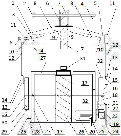
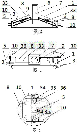
[0039] The present invention will be further described below in conjunction with the accompanying drawings and specific embodiments.
[0040] attached figure 1 . figure 2 . image 3 . Figure 4 Among them, a small forged belt hammer, including: impact hammer shell 1, upper frame 2, sliding sleeve 3, guide rod 4, shell support 5, impact hammer sliding sleeve 6, impact hammer 7, tire belt 8, impact hammer belt Ear 9, U-shaped adjustment screw 10, connecting rod upper bearing 11, connecting rod 12, connecting rod lower bearing 13, eccentric support shaft 14, pulley 15, main shaft 16, main shaft bearing seat 17, counterweight iron 18, motor pulley 19 , motor 20, elastic pressure wheel 21, elastic pressure wheel shaft 22, pressure wheel bracket 23, foot control device 24, foot control device support 25, mold pile 26, forged belt hammer frame 27, foot control device arm bar 28, Eccentric wheel 29, eccentric wheel counterweight throwing iron 30, Zheng or mold 31, flat belt 32, t...
PUM
Property
Measurement
Unit
diameter
aaaaa
aaaaa
length
aaaaa
aaaaa
power
aaaaa
aaaaa
Abstract
A small forging belt hammer comprises an impact hammer shell, guide rods, slide sleeves, an impact hammer, tire belts, U-shaped screws, connecting rods, a belt pulley, a spindle, counterweight iron, a motor, a tightening-loosening pinch roller, a foot-controlled device, a die pile, a frame, an eccentric wheel, a die, a flat plate belt, semicircular seat washers and adjusting nuts. The small forging belt hammer is characterized in that the slide sleeves are mounted on the shell, the guide rods are arranged in middles of the slide sleeves, upper ends of the guide rods are fixed through an upper frame while lower ends of the guide rods are mounted on the frame, and two sides of a waste tire are cut off while the middle portion contacting with the ground is reserved; each tire belt is mounted between each impact hammer belt lug and the corresponding U-shaped screw and locked by the corresponding screw, semicircular seats are welded to ends of the screws, the semicircular seat washers are arranged in middles of the semicircular seats, the adjusting nuts are mounted outside the semicircular seat washers, and the connecting rods are mounted on supporting pins; a spindle and spindle bearing seats are mounted on the frame, the belt pulley and the eccentric wheel are arranged on right and left of the spindle respectively and provided with counterweight iron, the flat plate belt is mounted on the belt pulley, and the die is mounted on the die pile. The small forging belt hammer is suitable for small hardware processing enterprises and worthy of wide popularization.
Description
technical field [0001] A small forging belt hammer belongs to the technical field of forging machinery. Background technique [0002] Forgings such as small hardware, mine road spikes, uranium nails, and grasping nails, it is labor-intensive to forge manually, the workers consume a lot of energy, the environment is not safe, and the cost is high; the equipment using hot pressing is very expensive, and mass production is not feasible. Corresponding demand market; forging with air hammer is not economical, and the cost is too high, which will increase the product cost; when the speed of small tension spring forging hammer is too high, it is easy to break the tension spring, which is only suitable for low-speed operation. Contents of the invention [0003] In order to solve the above problems, the present invention designs a small forged belt hammer for processing small hardware, which solves the problem of easily broken tension springs, and the tire belt is durable. [0004...
Claims
Application Information
Patent Timeline
Application Date:The date an application was filed.
Publication Date:The date a patent or application was officially published.
First Publication Date:The earliest publication date of a patent with the same application number.
Issue Date:Publication date of the patent grant document.
PCT Entry Date:The Entry date of PCT National Phase.
Estimated Expiry Date:The statutory expiry date of a patent right according to the Patent Law, and it is the longest term of protection that the patent right can achieve without the termination of the patent right due to other reasons(Term extension factor has been taken into account ).
Invalid Date:Actual expiry date is based on effective date or publication date of legal transaction data of invalid patent.