An electric oil drum handling device

A technology for handling devices and oil drums, which is used in transportation and packaging, motor vehicles, multi-axis trolleys, etc., can solve the problems of high labor cost and unsafe handling of oil drums, and achieve fast and convenient clamping, safe handling, and overall structure. simple effect

Active Publication Date: 2019-03-15
GUANGXI NANYIZAI SCI & TECH CO LTD
View PDF6 Cites 0 Cited by
  • Summary
  • Abstract
  • Description
  • Claims
  • Application Information

AI Technical Summary

Problems solved by technology

[0003] The object of the present invention is to provide an electric oil drum handling device to solve the problems of high manpower cost and unsafety in handling oil drums.

Method used


Image

  • An electric oil drum handling device
  • An electric oil drum handling device
  • An electric oil drum handling device

Examples


Embodiment Construction

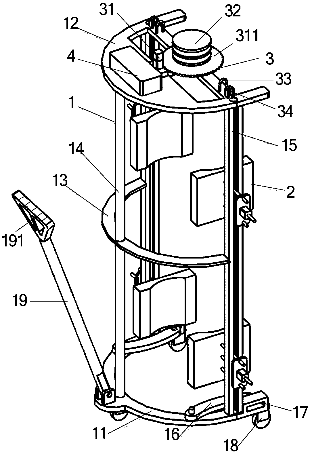
[0033] Such as figure 1 As shown, the oil drum handling device includes a frame 1 , a clamping part 2 and a lifting part 3 . The frame 1 is semi-cylindrical, the clamping part 2 is arranged symmetrically on both sides of the frame 1, the clamping part 2 is divided into upper and lower groups, the lifting part 3 is arranged on the upper end surface of the frame 1, and the rotation limiting device 4 is arranged on the The upper end surface is used to control the one-way rotation of the lifting part 3 . The frame 1 comprises a semi-arc bottom plate 11 arranged at the bottom, a top plate 12 is arranged directly above the bottom plate 11, and three uprights 14 are arranged between the bottom plate 11 and the top plate 12, and the three uprights 14 are respectively located in the middle and two ends of the bottom plate 11. The columns 14 at both ends of the bottom plate 11 are provided with guide rails 15 along the length direction of the columns, and the middle and both ends of th...


PUM


Abstract

The invention provides an electric oil bucket carrying device and belongs to the field of oil bucket carrying devices. The electric oil bucket carrying device comprises a frame, a clamping portion and a pull-lifting portion, wherein the frame comprises a semi-arc-shaped base plate at the lower portion, a top plate is arranged above the base plate, a vertical column and guide columns are arranged between the base plate and the top plate, the vertical column is arranged in the middle of the base plate, the guide columns are arranged at two ends of the base plate and provided with guide rails respectively, and wheels having self-locking functions are arranged in the middle and at two ends of the lower end face of the base plate. The clamping portion comprises moving parts arranged on the guide rails, wherein the moving parts are installed on the guide rails through wheel sets and slide along the guide rails. The pull-lifting portion comprises a driving device, a wire coil, a fixed pulley, a limiting ring and an upward pull rope. The problem that the labor cost for oil bucket carrying is high, and oil bucket carrying is unsafe and the like is solved.

Description

technical field [0001] The invention relates to the field of oil barrel handling equipment, in particular to an electric oil barrel handling device. Background technique [0002] In the manufacturing industry, it is often necessary to use a large amount of liquid auxiliary oil, such as drawing oil, lubricating oil, engine oil, etc. These auxiliary oils are generally stored in large iron drums or plastic drums, and these large oil drums are generally columnar structure, and the weight is relatively large, there is generally no handle on the oil drum, the workload of manual handling is large, and the handling efficiency is low; when the oil drum needs to be moved during the production process, usually multiple workers first lift the oil drum and put it on the handle On the truck, and then move the truck to the desired location, this method of transportation requires the cooperation of multiple people, and it is easy to cause bumps and other injuries to the workers during the p...

Claims


Application Information

Patent Timeline
Patent Type & Authority Patents(China)
IPC IPC(8): B62B3/04
CPCB62B3/04
Inventor 覃永红
Owner GUANGXI NANYIZAI SCI & TECH CO LTD
Why Eureka
Try Eureka