Deep well filling pressure release pipeline device and method

A technology for pressure relief pipelines and deep wells, which is applied in mining equipment, fillings, earthwork drilling, etc., can solve the problems of energy waste and wasteful energy, etc., and achieve the effect of improving efficiency, sufficient pressure relief, and high energy utilization rate. Effect

Pending Publication Date: 2017-11-28
CHINA MINMETALS CHANGSHA MINING RES INST
View PDF7 Cites 1 Cited by
  • Summary
  • Abstract
  • Description
  • Claims
  • Application Information

AI Technical Summary

Problems solved by technology

[0005] Its shortcoming is that the potential energy of the height difference of the slurry from the bottom surface to the bottom of the well is not utilized, but its energy is gradually consumed through the pressure relief box, resulting in energy waste; and the greater the height difference, the wasted energy more

Method used


Image

  • Deep well filling pressure release pipeline device and method
  • Deep well filling pressure release pipeline device and method
  • Deep well filling pressure release pipeline device and method

Examples


Embodiment 1

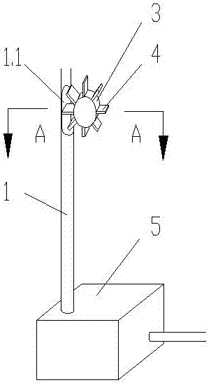
[0046] refer to figure 1 and 2 , a deep well filling pressure relief pipeline equipment, including a pipeline 1 and a pressure relief pool 5, the top of the pressure relief pool 5 is connected to the pipeline 1, and the tail is connected to another section of the pipeline 1, the side of the pipeline 1 is provided with an opening 1.1, and the opening 1.1 is provided Potential energy conversion device 2 is arranged.

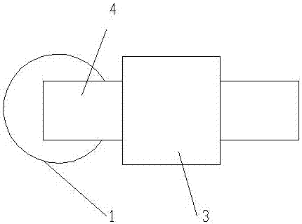
[0047] The potential energy conversion device 2 includes a main shaft 3 and a ring of baffles 4 around the main shaft 3; the baffles 4 extend into the opening 1.1.

[0048] When the baffle plate 4 is horizontal, the cross-sectional area of ​​the part extending into the opening 1.1 is 1 / 2 of the cross-sectional area of ​​the pipeline 1.

[0049] The lower diameter of the opening 1.1 on the side of the pipeline 1 is larger than the upper diameter.

[0050] The volume of the pressure relief pool is not less than 10 cubic meters.

[0051] The working principle of t...

Embodiment 2

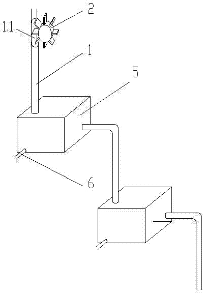
[0058] refer to image 3 and 4 , Embodiment 2 of the present invention is basically the same as Embodiment 1, the difference is:

[0059] The deep well filling pressure relief equipment provided by this embodiment includes two pressure relief pools 5, and also includes a pressure relief pool 5, the top of the pressure relief pool 5 is connected to the pipeline 1, and the tail is connected to the next section of the pipeline 1. The volume of the pressure relief pool 5 is greater than 10 cubic meters, the levels of the two pressure relief pools 5 are successively reduced.

[0060] A disturbance device is provided in the pressure relief pool 5 .

[0061] The disturbing device is a compressed air nozzle 6.1 installed at the bottom of the pressure relief pool 5, and the compressed air nozzle 6.1 is arranged on the air injection pipe 6, and the air injection pipe 6 extends from one side of the pressure relief pool 5.

[0062] The working principle of this embodiment is:

[0063]...

Embodiment 3

[0066] With reference to 5 and 6, embodiment 3 of the present invention is basically the same as embodiment 1, the difference is:

[0067] A disturbance device is provided in the pressure relief pool 5 .

[0068] The disturbance device is a stirring paddle 7, and the auxiliary shaft 8 extends from the top of the pressure relief pool 5, and the stirring paddle 7 is arranged at the bottom of the auxiliary shaft 8; one end of the main shaft 3 of the potential energy conversion device 2 is coaxially connected with a main bevel gear 9, the main cone The bevel gear 9 meshes with the secondary bevel gear 10, and the secondary bevel gear 10 is sleeved with the secondary shaft 8 at the center.

[0069] The working principle of this embodiment is:

[0070] The slurry falls from the pipeline 1, touches the baffle 4 on the way, and receives the resistance from the baffle 4 to achieve the effect of increasing resistance and energy dissipation; during this process, the kinetic energy of th...


PUM


Abstract

A deep well filling pressure release pipeline device comprises pipelines and pressure release tanks, the pressure release tanks are connected between the pipelines, one side of one pipeline is provided with an opening, and a potential energy conversion device is disposed at the opening. Slurry energy is collected and converted through the potential energy conversion device, slurry pressure of the pipelines is mitigated through the pressure release tanks, deep well filling slurry can be conveyed stably, the potential energy conversion device serves as a driving device of other deep well filling devices, potential energy of the slurry is effectively utilized, and linkage between the devices is increased. The invention also provides a deep well filling pressure release method comprising the steps that the slurry falls to the opening at the side of the pipeline and strikes baffle plates, and the baffle plates drive a main shaft to rotate; the slurry falls into the pressure release tank after striking the baffle plates; the main shaft transmits power to an auxiliary shaft and drives the auxiliary shaft to rotate; the auxiliary shaft drives stirring paddles to rotate; and the stirring paddles stir the slurry in the pressure release tank. According to the deep well filling pressure release method, the potential energy of the slurry serves as driving energy of the stirring shafts, the potential energy conversion device is linked with the stirring paddles, and integrity of the whole device is good.

Description

technical field [0001] The invention relates to the field of mine filling slurry transportation, in particular to a deep well filling pressure relief pipeline equipment and method. Background technique [0002] With the continuous exploitation of resources, mining needs to enter deep wells (below the surface of 800 meters), and the transportation of deep well filling slurry, the height difference from the surface to the bottom of the well is getting larger and larger, resulting in excessive pressure on the pipeline transportation of the slurry. However, the resistance of the pipeline is small, and there are unfavorable factors such as safety, pipeline wear, and operating costs in the pipeline transportation system. [0003] Most of the existing pipeline energy dissipation uses energy-dissipating orifice plates, but since the deep well filling slurry is mostly structured flow, that is, laminar flow, and the principle of energy-dissipating orifice plates is to increase the loc...

Claims


Application Information

Patent Timeline
Patent Type & Authority Applications(China)
IPC IPC(8): E21F15/00
CPCE21F15/00
Inventor 郑伯坤李向东盛佳邓高岭
Owner CHINA MINMETALS CHANGSHA MINING RES INST
Why Eureka
Try Eureka