Test bench and test method of chassis driving test of robot

A driving test, robot technology, applied in the test of machine/structural components, motor generator test, mechanical component test, etc., can solve the problem that the motor operating point data cannot be captured, the motor driving ability, the efficiency and the chassis endurance are unpredictable and unpredictable. Design evaluation, long development time, etc.

Pending Publication Date: 2017-11-28
北京云迹科技股份有限公司
View PDF8 Cites 2 Cited by
  • Summary
  • Abstract
  • Description
  • Claims
  • Application Information

AI Technical Summary

Problems solved by technology

At present, most of the chassis drive test is the actual terrain test after the whole machine comes out, so the product development time is long, and the data of the motor wor

Method used


Image

  • Test bench and test method of chassis driving test of robot
  • Test bench and test method of chassis driving test of robot
  • Test bench and test method of chassis driving test of robot

Examples


Embodiment approach 1

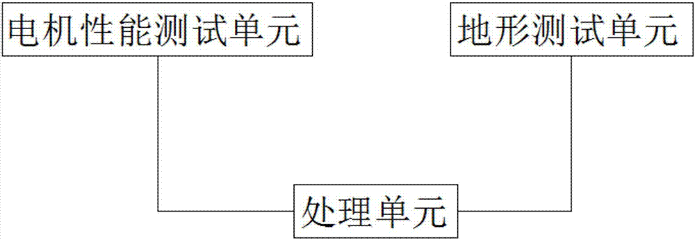
[0036] According to one aspect of the present invention there is provided a robot chassis drive test bench, comprising:

[0037] The motor performance test unit, the motor performance test unit includes: a first dynamometer and a first transmission device, the first dynamometer is connected to one end of the first transmission device, and the output shaft of the motor to be tested is connected to the other end of the transmission device during use ;

[0038] The terrain test unit, the terrain test unit includes: the second dynamometer and the second transmission device;

[0039] Wherein, the second transmission device includes a terrain transmission shaft and a terrain sleeve, one end of the terrain transmission shaft is connected to the second dynamometer, the terrain sleeve is sleeved on the terrain transmission shaft, and the motor to be tested is in contact with the terrain sleeve during use. The motor to be tested can drive the terrain sleeve to rotate;

[0040] Wherein...

Embodiment 1

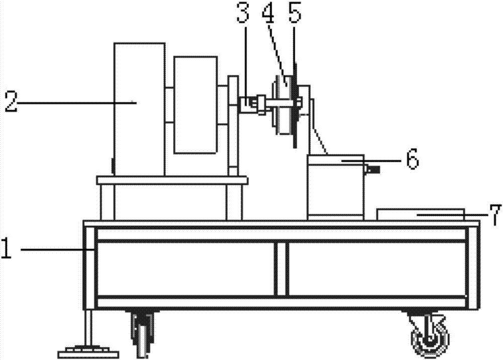
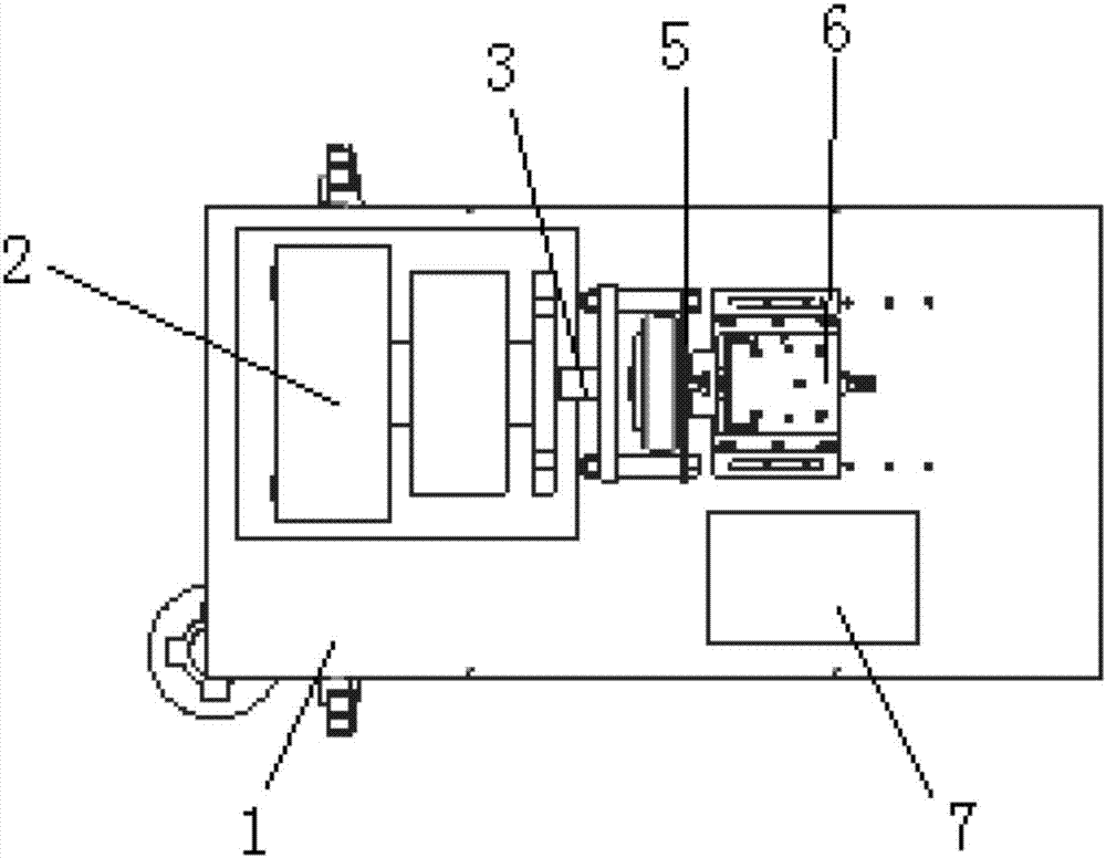
[0060] figure 1 A schematic structural diagram of a robot chassis driving test bench according to an embodiment of the present invention is shown. figure 2 A front view of a motor performance testing unit according to an embodiment of the present invention is shown. image 3 A top view of a motor performance testing unit according to an embodiment of the present invention is shown. Figure 4 A left side view of the motor performance testing unit according to an embodiment of the present invention is shown. Figure 5 A front view of a terrain testing unit according to an embodiment of the present invention is shown. Figure 6 A top view of a terrain testing unit according to an embodiment of the present invention is shown. Figure 7 A left side view of a terrain testing unit according to one embodiment of the invention is shown.

[0061] Such as Figure 1-7 As shown, the robot chassis drives the test bench, including:

[0062] The motor performance test unit, the motor p...

Embodiment approach 2

[0071] According to another aspect of the present invention there is provided a robot chassis drive test method, the robot chassis drive test method comprising:

[0072] Connect the output shaft of the motor to be tested to the first transmission device, start the motor to be tested to obtain the motion parameters of the motor to be tested through the first dynamometer, and send the motion parameters to the processing unit;

[0073] Specifically, when in use, the first dynamometer applies a load to the motor to be tested, and the load is selected according to actual needs. The first dynamometer obtains the motion parameters of the motor to be tested, and the user can obtain the motion parameters of the motor to be tested through the processing unit. The parameters are compared with the motion parameters of the actual required motor, and then it is determined that the motor to be tested can meet the requirements of normal use.

[0074] Remove the motor to be tested, and connect...


PUM


Abstract

The invention discloses a test bench and a test method of a chassis driving test of a robot. The test bench comprises a motor performance test unit, a landform test unit and a processing unit. The motor performance test unit comprises a first power test machine and a first transmission device. The first power test machine is connected to one end of the first transmission device. In use, the output shaft of a to-be-tested motor is connected to the other end of the transmission device. The landform test unit comprises a second power test machine and a second transmission device. The second transmission device comprises a landform transmission shaft and a landform sleeve. One end of the landform transmission shaft is connected to the second power test machine. The landform sleeve sleeves the landform transmission shaft. In use, the to-be-tested motor contacts the landform sleeve and is capable of driving the landform sleeve to rotate. The motor performance test unit and the landform test unit are in communication connection with the processing unit. According to the invention, a test and experiment bench is provided for testing, evaluation, optimization and reliability testing of the chassis driving system and a chassis comprehensive test system is established.

Description

technical field [0001] The invention relates to the field of performance detection, in particular to a robot chassis drive test bench and a test method. Background technique [0002] The robot chassis drive is the walking part of the robot, including the chassis structure, drive motor, drive board, power board, etc. Its basic working principle is that the upper computer (computer) gives a movement command, calculates through the drive board, and drives the motor to work, thereby completing the robot's indoor walking. At present, most of the chassis drive tests are the actual terrain tests after the whole machine comes out, so the product development time is long, and the typical terrain motor operating point data cannot be captured, and the motor drive capability, efficiency, and chassis endurance cannot be predicted and evaluated. In particular, the driving wheel motor is a key component of the robot chassis drive. Its dynamic performance and reliability determine the over...

Claims


Application Information

Patent Timeline
IPC IPC(8): G01M13/00G01R31/34
CPCG01M13/00G01R31/34
Inventor 应甫臣周发文
Owner 北京云迹科技股份有限公司
Why Eureka
Try Eureka