Automated laser diode test system

a laser diode and test system technology, applied in the field of reliability test systems, can solve the problems of limited capacity of existing wave-guiding media, prohibitive expansion cost, and limited capacity of current wave-guiding media

Inactive Publication Date: 2005-03-29
BANDWIDTH9
View PDF9 Cites 3 Cited by
  • Summary
  • Abstract
  • Description
  • Claims
  • Application Information

AI Technical Summary

Benefits of technology

Yet another object of the present invention is to provide an improved automated test system, and its methods of use that provides automation of a testing procedure by automatically calibrating each laser to a corresponding photodetector, and establishing communication between all key test system component.

Problems solved by technology

While this is a useful technique for carrying plural information sources on a s single channel, its capacity is limited by fiber dispersion and the need to generate high peak power pulses.
While the need for communication systems increases, the current capacity of existing wave-guiding media is limited.
Although capacity may be expanded, e.g. by laying more fiber optic cables, the cost of such expansion is prohibitive.
Some of the devices, however, will continue to shift during the operation until they ultimately fail, and also cause the ultimate failure of the communications system.
Most laboriously, the photodetector calibration, required to be done at start of each measurement, when done manually, is very time consuming and needs to be repeated with regularity.

Method used


Image

  • Automated laser diode test system
  • Automated laser diode test system
  • Automated laser diode test system

Examples


Embodiment Construction

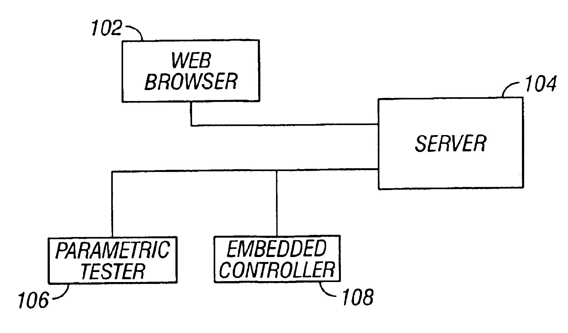
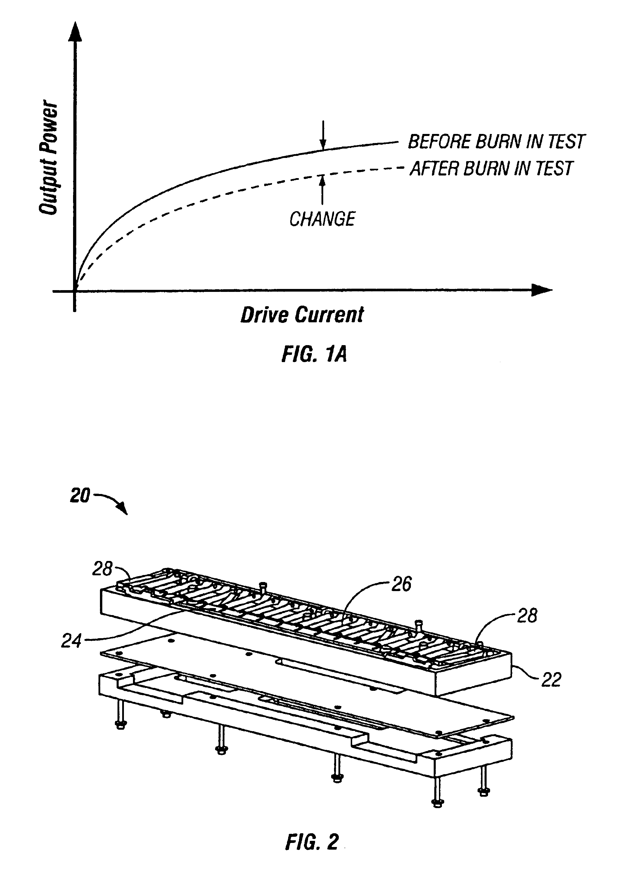
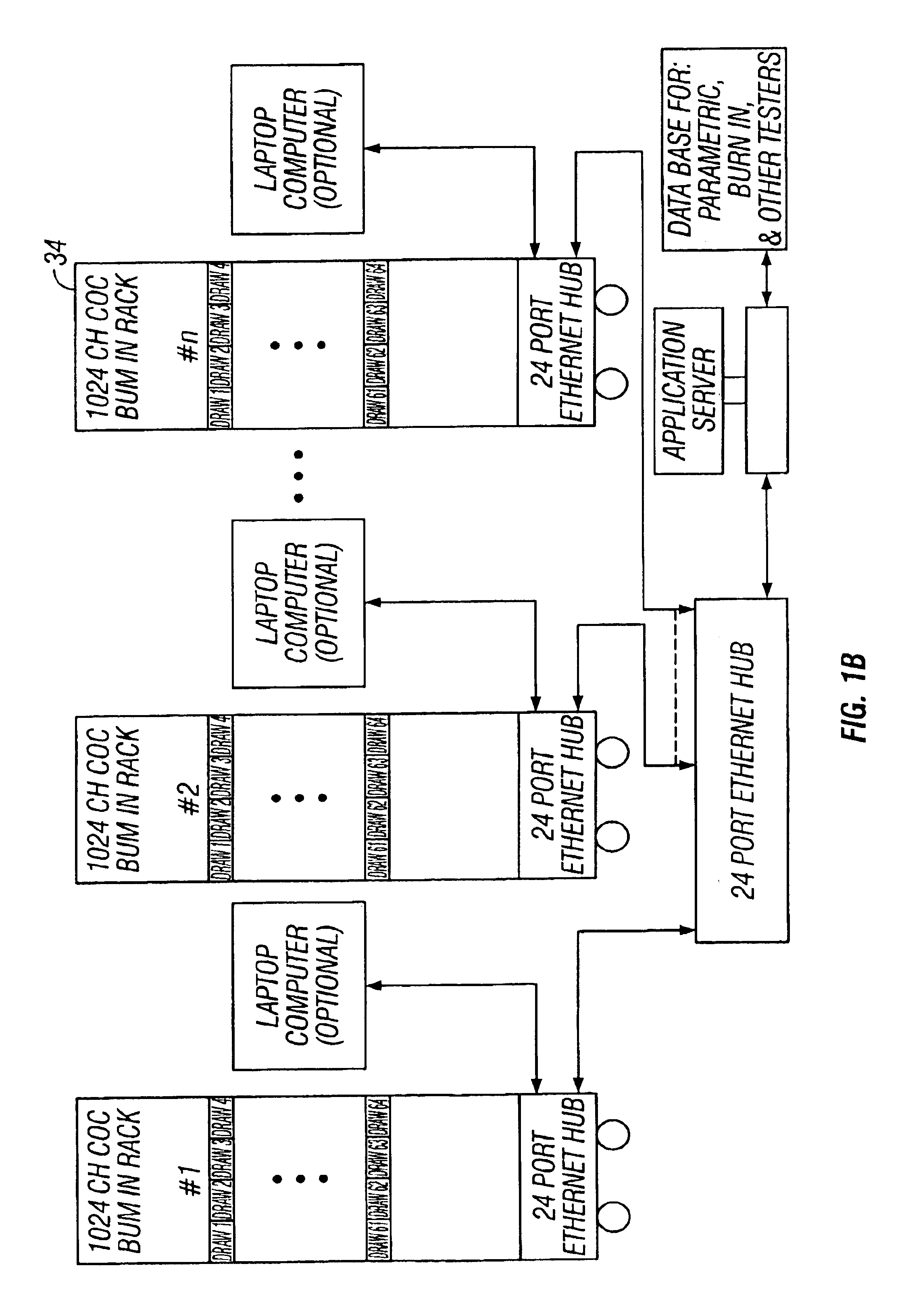
In various embodiments, the present invention provides test systems, and their methods of use, for automatically testing light emitting devices including but not limited to lasers. In one embodiment, the devices are subjected to an electrical test where an appropriate amount of current is applied according to the type of the device. The test system records the power output for each device. Other parameters also may be recorded. The devices are then subjected to a burn-in process for a period of time. Upon completion of the burn-in process the devices are allowed to cool to room temperature. The same test done before the burn-in is now repeated. The amount of change form the initial reading is recorded for each device. Devices that exceed the amount of allowable change are rejected. Those that remain within specification are passed on to the next level of assembly. The test system stores all the test data and the date may be retrieved for each device directly or remotely form the tes...


PUM


Abstract

An automated laser diode testing and burn-in system is disclosed. Initial device data is obtained by applying current to the device at room temperature and measuring the device parameters. The device is then subjected to a burn-in process at higher temperatures. Device performance is monitored throughout the burn-in process. Upon termination of the burn-in process the devices are cooled to room temperature and the post burn-in device power is measured again under the same test conditions. If the device parameters have changed by more than a particular amount the device is rejected. Otherwise, the device is accepted and installed in the next level assembly. The test system disclosed herein achieves significant advantages over prior art in cost and throughput by combining an easy to load laser test fixture with automatic device hold down feature, heating capability, computer program driven test protocol capable of performing initial laser measurements, calibrating each laser and photodetector pair, burn-in test, post burn-in measurements, failed device detection, storage of laser test history records and enabling remote access to such records. The invention eliminates the need for numerous labor intensive ergonomically difficult steps and costly test fixtures.

Description

BACKGROUND OF THE INVENTION1. Field of the InventionThis invention relates to the field of reliability test systems, and more particularly to a test system that tests the reliability of optical devices such as diode lasers, and more specifically, tunable lasers.2. Description of Related ArtLaser diodes are a substantial and fast growing constituent of optical communications networks. Such optical systems include, but are not limited to, telecommunication systems, cable television systems, and Local Area Networks (LANs). Optical systems are described in Gowar, Ed. Optical Communication Systems, (Prentice Hall, N.Y.) c. 1993 and Agrawal, G. Fiber-Optic Communications System, Wiley, 1997, the disclosures of which are incorporated herein by reference. Currently, the majority of optical systems are configured to carry an optical channel of a single wavelength over one or more optical wave-guides. To convey the information form plural sources, time division multiplexing is frequently empl...

Claims


Application Information

Patent Timeline
Patent Type & Authority Patents(United States)
IPC IPC(8): H01S5/00H01S5/042
CPCH01S5/0014H01S5/042H01S5/0021
Inventor CORNELIUS, PAULWALSH, JOHNYIM, YONG
Owner BANDWIDTH9
Why Eureka
Try Eureka