
Method and apparatus for recording the viewing direction of a person

A device and field of view technology, applied in the field of field of view equipment and computer program products, can solve problems such as incorrect interpretation of pupil position and pupil size, and failure to take into account field distortion, etc., to achieve the effect of improved stability and rapid correction

Inactive Publication Date: 2017-11-28
ROBERT BOSCH GMBH
View PDF7 Cites 0 Cited by
  • Summary
  • Abstract
  • Description
  • Claims
  • Application Information

AI Technical Summary

Problems solved by technology

Thus, depending on the thickness and geometry of the vision aid, an incorrect interpretation of the detected pupil position and pupil size into the viewing angle may result, since the corresponding field of view due to the vision aid used is not taken into account distortion

Method used


Image

  • Method and apparatus for recording the viewing direction of a person

Examples


Embodiment Construction

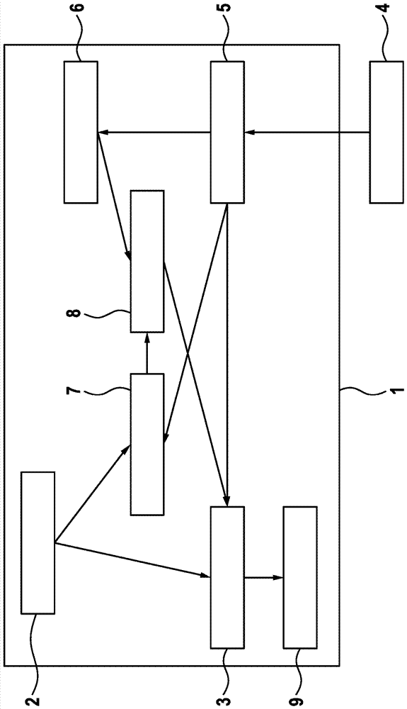
[0022] figure 1 A system or device 1 for detecting the direction of view of a person is shown. The device 1 includes a viewing device 2 , for example in the form of one or more driver viewing cameras. The viewing device 2 records individual images or a sequence of images and supplies these images to a computing device 3 , such as a control device of an auxiliary system. One or more images of the viewing device 2 are analyzed in the computing device 3 . For this purpose, first one or both pupils can be located in the data of the viewing device 2 , and then a field of view vector can be formed, for example, from the position and size of the pupil or pupils. The view direction vector indicates in which direction the observed person is looking. What can also be explained is what or how far a person's field of vision focuses.

[0023] If the observed person is using a vision aid, such as spectacles or contact lenses, the eyes or pupils are behind the vision aid from the perspec...


PUM


Abstract

The invention relates to a method for recording the viewing direction of a person having a vision aid comprising the steps of providing at least one optical property of a vision aid of the person; observing at least one eye of the person, and correcting data determined from the observation on the basis of the at least one optical property of the vision aid. An apparatus (1) set up to record the viewing direction of a person comprises an observation device (2) equipped to observe at least one eye of the person, a data set (5) containing at least one optical property of a vision aid of the person, and a computing device (3) equipped to correct the observation on the basis of the data set (5).

Description

technical field [0001] The invention relates to a method for detecting the direction of view of a person, a device designed for detecting the direction of view of a person, and a computer program product. Background technique [0002] Field-of-view detection systems are known, for example, from vehicles or electronic devices such as entertainment electronics or consumer electronics. Such view direction detection systems typically detect the position and size of the pupils of the observed person. [0003] Such systems do not take into account possible vision aids such as spectacles or contact lenses. Thus, depending on the thickness and geometry of the vision aid, an incorrect interpretation of the detected pupil position and pupil size into the viewing angle may result, since the corresponding field of view due to the vision aid used is not taken into account distortion. Contents of the invention [0004] According to the invention, a method for detecting the direction ...

Claims


Application Information

Patent Timeline
IPC IPC(8): A61B3/10
CPCA61B3/10A61B3/113B60W40/08B60W2050/0085B60W2540/225G02B27/0093G03B13/02G03B2213/025
Inventor A.韦尔克尔
Owner ROBERT BOSCH GMBH
Learn More