Synchronization control device for power converter

A power converter and synchronous control technology, applied in the direction of electronic commutation motor control, motor generator control, AC motor control, etc., can solve the problem of insufficient effect and achieve the effect of accurate current control

Active Publication Date: 2017-11-28
MEIDENSHA ELECTRIC MFG CO LTD
View PDF6 Cites 0 Cited by
  • Summary
  • Abstract
  • Description
  • Claims
  • Application Information

AI Technical Summary

Problems solved by technology

However, the technique of Patent Document 1 is not effective in suppressing overcurrent because the current control of the inverter INV is not directly performed at the time of switching operation

Method used


Image

  • Synchronization control device for power converter
  • Synchronization control device for power converter
  • Synchronization control device for power converter

Examples


Embodiment 1

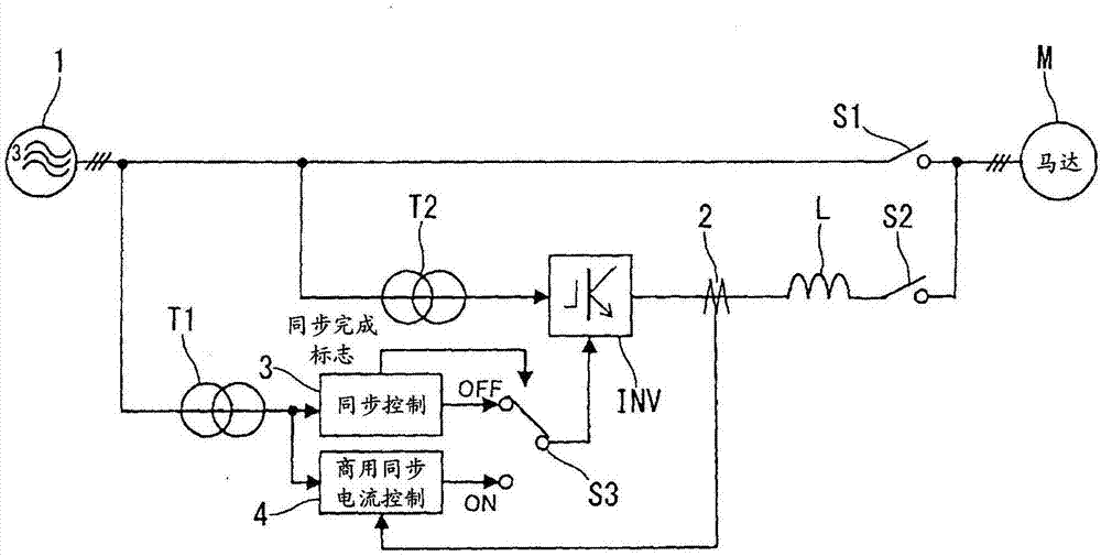
[0060] figure 1 The synchronous control device of the power converter according to the first embodiment is schematically shown. The commercial power supply or mains power supply 1 is a three-phase ac power supply. An on / off switch or an on / off switch S1 for driving by the commercial power supply 1 is connected between the commercial power supply 1 and the motor M. As shown in FIG. The series circuit is connected in parallel with the on / off switch S1 for commercial power supply. This series circuit is a series combination of an input transformer T2, an inverter INV, an ac reactor L and an on / off switch or an on / off switch S2 for the inverter INV. The current sensor 2 is provided on the output side of the inverter INV for sensing three-phase sense currents Iu, Iv, and Iw of the inverter INV. The on / off switches S1 and S2 are turned on or off to switch the driving of the motor between commercial power supply or driving by the commercial power supply 1 and inverter driving or i...

Embodiment 2

[0101] In the second embodiment, a low-pass filter LPF is added to the commercial synchronous current control section 4 of the first embodiment.

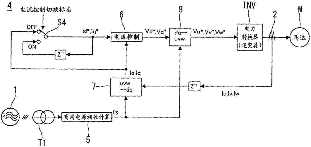
[0102] Figure 4 The commercial synchronous current control section 4 of the second embodiment is shown in a block diagram.

[0103] In the second embodiment, as Figure 4 As shown in , the low-pass filter LPF is connected between the three-phase to two-phase conversion section 7 and the changeover switch S4. The d-axis sensing current Id and the q-axis sensing current Iq may include an offset component due to the residual magnetic flux of the HCT used as the current sensor and the circuit error of the current sensor 2, and the output frequency generated by the shift of the sensing gain first and second harmonic components. In addition, noise superimposed in the current sensor 2 is also superimposed on the d-axis sense current Id and the q-axis sensor current Iq.

[0104] If these disturbances are superimposed, the d-axis sense ...

Embodiment 3

[0108] Figure 5 The commercial synchronous current control section 4 according to the third embodiment is shown in a block diagram. In the third embodiment, such as Figure 5As shown in , an attenuation processing section 9 is provided between the changeover switch S4 and the current control section 6 . After the output voltage of the inverter INV overlaps with the output voltage of the commercial power supply 1, figure 1 On / off switch S2 for inverter operation shown in is open. In this case, if the current on the commercial power supply side is almost equal to zero and the current on the inverter side is almost equal to the motor current when this on / off switch S2 is off, then the current on the commercial power supply side is transferred from the inverter due to the supply of driving power side switching to the commercial power supply side increases instantaneously, and the switching operation may become unstable. Therefore, the attenuation processing section 9 graduall...


PUM


Abstract

A synchronization control unit 3 operates a power converter INV by means of V/f control, with a first on/off switch S1 being "off" and a second on/off switch S2 being "on". A utility synchronization current control unit 4 operates the power converter INV by means of V/f control, with the first on/off switch S1 being "off" and the second on/off switch S2 being "on", until the rotation speed of a motor M reaches a predetermined value, and changes the control of the power converter INV to current control based on a current detection value detected by a current sensor 2 once the rotation speed of the motor M has reached the predetermined value. Thereafter, the utility synchronization current control unit turns the first on/off switch S1 "on" to supply power to the motor M from both the power converter INV and a utility power supply 1, then turns the second on/off switch S2 "off" to supply power to the motor M from the utility power supply 1. Consequently, the synchronization control device for the power converter can perform more accurate current control and allows for a stable transition from power converter-based driving to utility power supply-based driving.

Description

technical field [0001] The present invention relates to a control technique for driving an electric motor (hereinafter referred to as a motor) using a commercial power source with a control method of starting the motor by using a power converter, synchronizing the power converter with the commercial power source, and changing the mode of driving the motor from The power converter drive is switched to commercial power drive. Background technique [0002] In a system for driving a motor with a commercial power supply or a mains power supply, the starting operation is easier in the direct start (full voltage start) mode. However, in this case, starting torque up to motor rating or rated torque And the starting current is up to the rated current of the motor Therefore, the starting operation in this mode requires a large-capacity commercial power supply suitable for the required starting current. [0003] In order to reduce the capacity of a commercial power supply, there i...

Claims


Application Information

Patent Timeline
Patent Type & Authority Applications(China)
IPC IPC(8): H02P1/46H02P21/34
CPCH02M7/48H02P1/46H02P21/34H02P1/42H02P27/06
Inventor 毛塚信贵宫本恭昌
Owner MEIDENSHA ELECTRIC MFG CO LTD
Why Eureka
Try Eureka