Synchronous control equipment for power converters
A power converter and synchronous control technology, applied in the direction of electronic commutation motor control, motor generator control, AC motor control, etc., can solve problems such as insufficient effects
- Summary
- Abstract
- Description
- Claims
- Application Information
AI Technical Summary
Problems solved by technology
Method used
Image
Examples
Embodiment 1
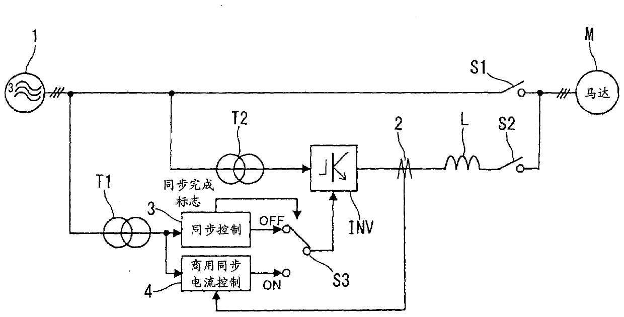
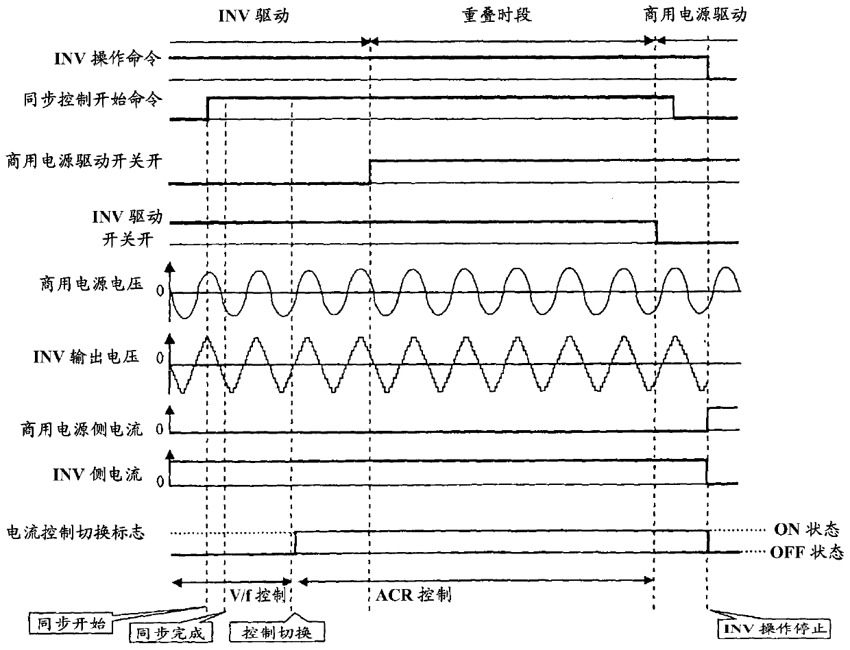
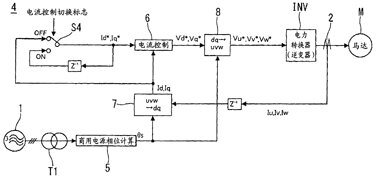
[0060] figure 1 The synchronous control device of the power converter according to the first embodiment is schematically shown. The commercial power supply or mains power supply 1 is a three-phase ac power supply. An on / off switch or an on / off switch S1 for driving by the commercial power supply 1 is connected between the commercial power supply 1 and the motor M. As shown in FIG. The series circuit is connected in parallel with the on / off switch S1 for commercial power supply. This series circuit is a series combination of an input transformer T2, an inverter INV, an ac reactor L and an on / off switch or an on / off switch S2 for the inverter INV. The current sensor 2 is provided on the output side of the inverter INV for sensing three-phase sense currents Iu, Iv, and Iw of the inverter INV. The on / off switches S1 and S2 are turned on or off to switch the driving of the motor between commercial power supply or driving by the commercial power supply 1 and inverter driving or i...
Embodiment 2
[0103] In the second embodiment, a low-pass filter LPF is added to the commercial synchronous current control section 4 of the first embodiment.
[0104] Figure 4 The commercial synchronous current control section 4 of the second embodiment is shown in a block diagram.
[0105] In the second embodiment, as Figure 4 As shown in , the low-pass filter LPF is connected between the three-phase to two-phase conversion section 7 and the changeover switch S4. The d-axis sensing current Id and the q-axis sensing current Iq may include an offset component due to the residual magnetic flux of the HCT used as the current sensor and the circuit error of the current sensor 2, and the output frequency generated by the shift of the sensing gain first and second harmonic components. In addition, noise superimposed in the current sensor 2 is also superimposed on the d-axis sense current Id and the q-axis sensor current Iq.
[0106] If these disturbances are superimposed, the d-axis sense ...
Embodiment 3
[0110] Figure 5 The commercial synchronous current control section 4 according to the third embodiment is shown in a block diagram. In the third embodiment, such as Figure 5 As shown in , an attenuation processing section 9 is provided between the changeover switch S4 and the current control section 6 . After the output voltage of the inverter INV overlaps with the output voltage of the commercial power supply 1, figure 1 On / off switch S2 for inverter operation shown in is open. In this case, if the current on the commercial power supply side is almost equal to zero and the current on the inverter side is almost equal to the motor current when this on / off switch S2 is off, then the current on the commercial power supply side is transferred from the inverter due to the supply of driving power side switching to the commercial power supply side increases instantaneously, and the switching operation may become unstable. Therefore, the attenuation processing section 9 gradual...
PUM
 Abstract
Description
Claims
Application Information
 - R&D
- Intellectual Property
- Life Sciences
- Materials
- Tech Scout
- Unparalleled Data Quality
- Higher Quality Content
- 60% Fewer Hallucinations
Browse by: Latest US Patents, China's latest patents, Technical Efficacy Thesaurus, Application Domain, Technology Topic, Popular Technical Reports.
© 2025 PatSnap. All rights reserved.Legal|Privacy policy|Modern Slavery Act Transparency Statement|Sitemap|About US| Contact US: help@patsnap.com


