A laser marking machine focusing method, device and laser marking machine

A laser marking machine and marking head technology, applied in the field of laser marking, can solve problems such as poor marking effect, inability to achieve accurate focus adjustment, difficulty in making accurate judgments and adjustments, and achieve high consistency and overcome Invisibility, the effect of improving the marking effect

Active Publication Date: 2018-08-07
MAXPHOTONICS CORP
View PDF4 Cites 0 Cited by
  • Summary
  • Abstract
  • Description
  • Claims
  • Application Information

AI Technical Summary

Problems solved by technology

But this method is only suitable for experienced marking engineers, who can judge the increase or decrease of the focal length according to the marking effect, but it is difficult for inexperienced users such as first-time users to make accurate judgments and adjustments. Unable to achieve accurate focusing, so that the final marking effect is poor

Method used


Image

  • A laser marking machine focusing method, device and laser marking machine
  • A laser marking machine focusing method, device and laser marking machine
  • A laser marking machine focusing method, device and laser marking machine

Examples


Embodiment 1

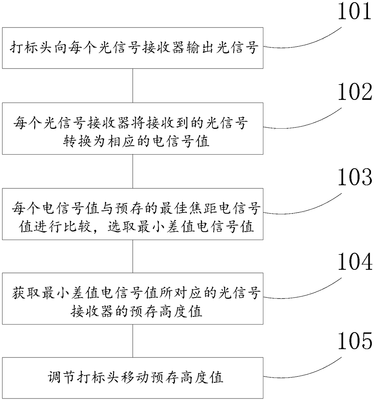
[0037] figure 1 A focusing method of a laser marking machine provided by an embodiment of the present invention. Wherein, the laser marking machine includes a marking head and a laser marking machine focusing device arranged under the marking head, and the laser marking machine focusing device includes a plurality of optical signal receivers corresponding to different pre-stored height values; the method includes :

[0038] Step S101: Adjust the marking head to the highest point, and the marking head outputs optical signals to each optical signal receiver; in practical applications, the optical signal receivers are arranged and installed step by step, that is, each optical signal The signal receivers are at different gradient heights, the marking head outputs laser light, and each optical signal receiver is marked one by one from the bottom along the slope of the ladder.

[0039] Step S102: Each optical signal receiver converts the received optical signal into a correspondin...

Embodiment 2

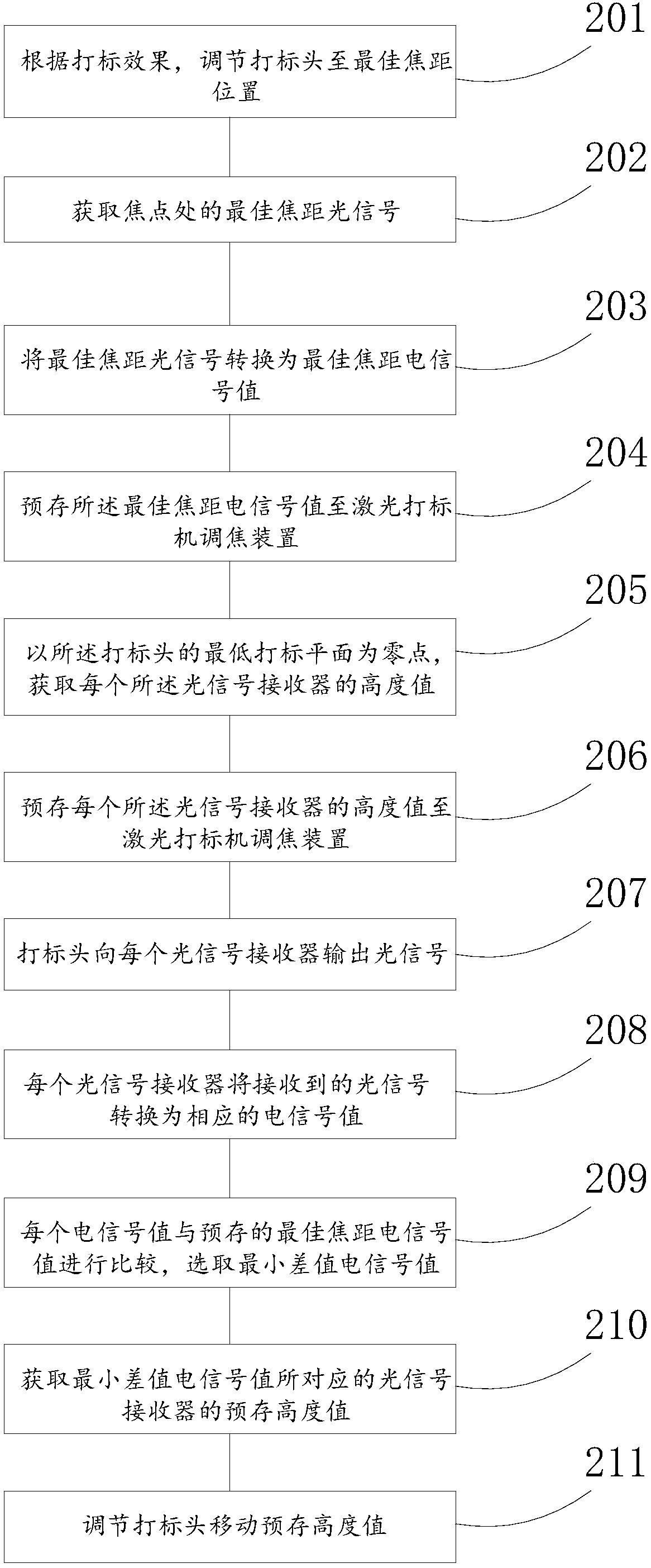
[0045] figure 2 Another laser marking machine focusing method provided by the embodiment of the present invention. The method includes:

[0046] Step S201: Put the workpiece on the workbench of the laser marking machine, perform trial marking on the workpiece, and adjust the marking head to the best focal length position according to the marking effect;

[0047] Step S202: Obtain the optical signal with the best focal length at the focal point; at this time, the height of the marking plane of the workpiece is the height of the focal point, and the intensity of the optical signal at the focal point is the optical signal with the optimal focal length.

[0048] Step S203: convert the best focal length optical signal into the best focal length electrical signal value; convert the intensity of the laser light signal at the focal point into an electrical signal value, and this electrical signal value is the best focal length electrical signal value, the electrical signal value Ca...

Embodiment 3

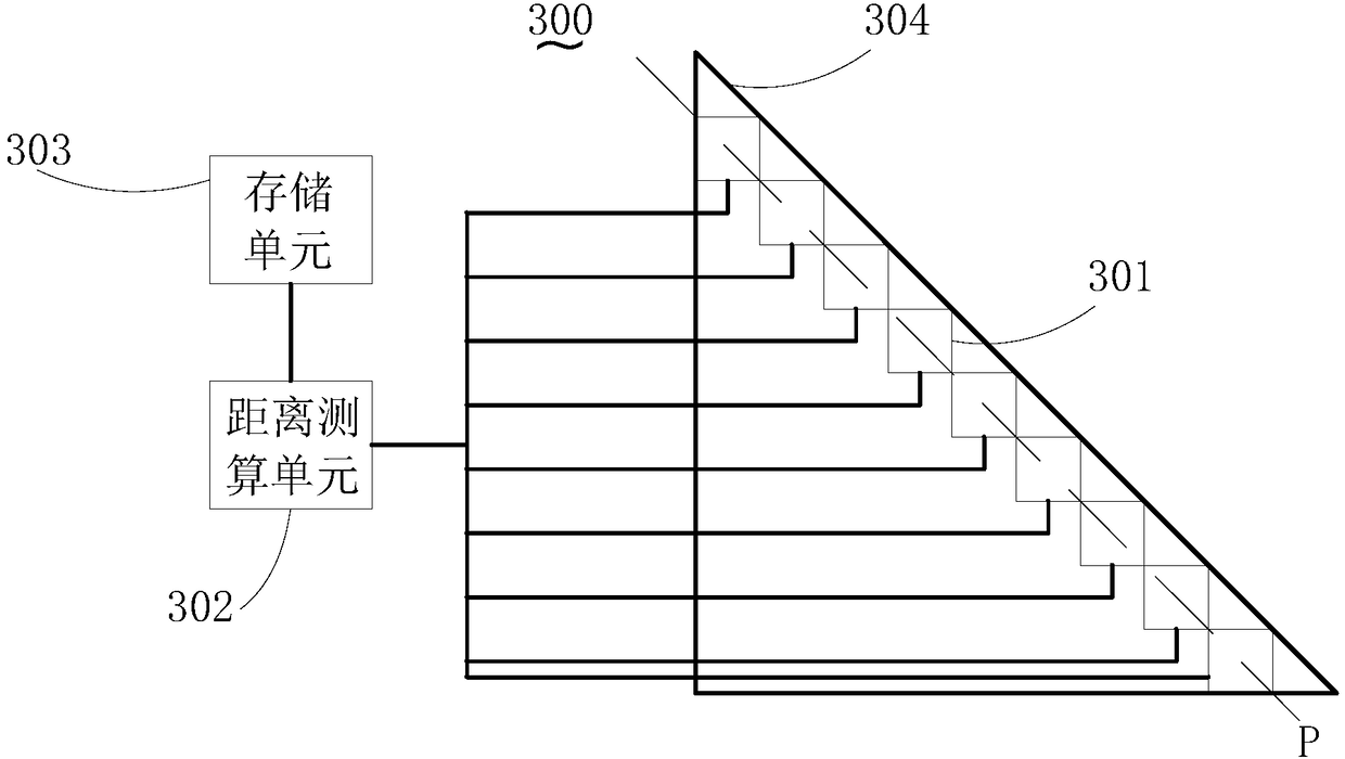
[0059] image 3 A focusing device for a laser marking machine provided by an embodiment of the present invention. The focusing device 300 of the laser marking machine includes: a base 304 , a plurality of optical signal receivers 301 , a distance measuring unit 302 and a storage unit 303 .

[0060] The base 304 is used for installing the optical signal receiver 301 . In this embodiment, the base 304 is a hollow triangular prism, and a plurality of optical signal receivers 301 can be installed on the base 304 by means of adhesion, welding or screw connection.

[0061] The optical signal receiver 301 is used to receive the optical signal from the laser marking machine. In practical applications, the optical signal receiver 301 may be a photoelectric sensor with a photoelectric signal conversion function, such as a photoresistor, a phototransistor, and the like. A plurality of optical signal receivers 301 are arranged and installed on the base 304 in a stepped manner along an ...


PUM


Abstract

The invention provides a focusing method and device for a laser marking machine and the laser marking machine. The focusing method for the laser marking machine comprises the steps that a marking head outputs an optical signal to each optical signal receiver; each optical signal receiver converts the received optical signal into a corresponding electrical signal value; each electrical signal value is compared with a prestored optimum focal distance electrical signal value, and a minimum difference value electrical signal value is selected; a prestored height value of the optical signal receiver corresponding to the minimum difference value electrical signal value is acquired; and the marking head is adjusted to move by the prestored height value. According to the focusing method and device for the laser marking machine and the laser marking machine, the invisibility of laser is overcome, the invisible laser is converted into the quantifiable electrical signal values, moreover, the electrical signal values are compared with the optimum focal distance electrical signal value, so that the value of the height difference between a focus and a marking plane is obtained, and the marking head can be directly adjusted according to the value of the height difference; and focusing operation is simple, focusing is accurate, the consistency is high, and the marking effect of the laser marking machine is enhanced greatly.

Description

technical field [0001] The invention relates to the technical field of laser marking, in particular to an automatic focusing method and device for a laser marking machine and a laser marking machine. Background technique [0002] Laser marking machine is to use laser beam to make permanent marks on the surface of various materials. The effect of laser marking is to expose the deep material through the evaporation of the surface material, so as to carve exquisite patterns, trademarks and characters. [0003] Before laser marking, it is necessary to adjust the focal length of the laser marking machine. The existing focusing method is to use metal business cards or other sensitive materials for trial marking. According to the marking effect, adjust the focal length while trial marking, and so on. , until the best marking effect is achieved, then the focal length at this time is considered to be the best focal length, and the laser marking machine focus is completed to mark the...

Claims


Application Information

Patent Timeline
Patent Type & Authority Patents(China)
IPC IPC(8): B23K26/046B23K26/364
CPCB23K26/046B23K26/364
Inventor 武晓花蒋峰
Owner MAXPHOTONICS CORP
Why Eureka
Try Eureka