Eureka AIR delivers breakthrough ideas for toughest innovation challenges, trusted by R&D personnel around the world.

Force transmission vehicle frame

A frame and beam technology, applied in the field of body structure, can solve the problems of small ground clearance, large space utilization, heavy weight, etc.

Active Publication Date: 2017-12-01
SAIC-GM-WULING AUTOMOBILE CO LTD
View PDF6 Cites 3 Cited by
  • Summary
  • Abstract
  • Description
  • Claims
  • Application Information

AI Technical Summary

Problems solved by technology

[0002] At present, the frame has a complete longitudinal beam structure, which takes a large space and is heavy. The frame generally adopts a non-semi-load-bearing frame structure or a load-bearing body structure. The three girders are on the same level, and there is no overlap between the front girder and the rear girder of the load-bearing body structure. The ground clearance is small; there is no joint structure, and the transition is very sharp; the A / B / C column overlap structure is simple, the force transmission path is single, and the structural strength is low

Method used


Image

  • Force transmission vehicle frame
  • Force transmission vehicle frame
  • Force transmission vehicle frame

Examples


Embodiment Construction

[0020] The specific implementation of a force transmission frame of the present invention will be further described in detail below with reference to the drawings and embodiments. The following examples are used to illustrate the present invention, but are not intended to limit the scope of the present invention.

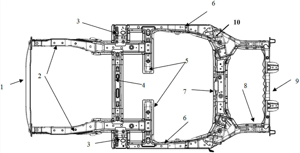
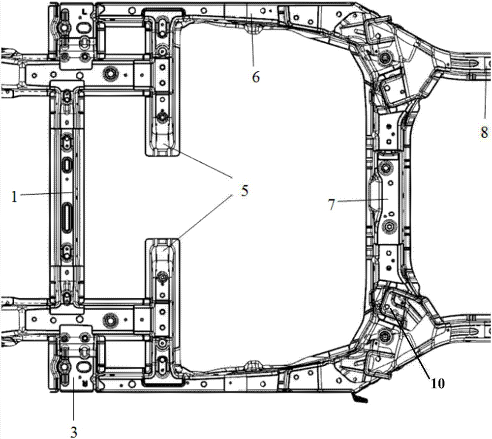
[0021] Such as Figure 1-6 As shown, a force transmission vehicle frame of the present invention includes a front beam 1, a rear beam 9, an extension 3, a first beam 4, a rear floor beam 7, two second beams 5, two front beams 2, two A rear girder reinforcement plate 6 and two rear girders, the two front girders 2 are arranged in parallel, one end of the two front girders 2 is respectively fixedly connected to the left and right ends of the front cross beam 1, and the other ends of the two front girders 2 Two described second crossbeams 5 are vertically fixedly connected respectively, and first crossbeam 4 is arranged between described front crossbeam 1 and describe...


PUM


Abstract

The invention discloses a force transmission vehicle frame comprising a front cross beam, a rear cross beam, extending pieces, a first cross beam, a rear floor cross beam, two second cross beams, two front large beams, two rear large beam strengthening plates and two rear large beams. The two front large beams are parallelly arranged; one ends of the two front large beams are fixedly connected with the left end and the right end of the front cross beam correspondingly, and the other ends of the two front large beams are perpendicularly and fixedly connected with the two second cross beams correspondingly; the first cross beam is arranged between the front cross beam and the second cross beams; the two ends of the first cross beam are perpendicularly and fixedly connected with the two front large beams correspondingly; the two rear large beam strengthening plates are arranged on the two rear large beams correspondingly; one ends of the two rear large beams are connected with the two rear large beams strengthening plates through the extending pieces, and the other ends of the two rear large beams are perpendicularly connected with the rear cross beam; and the two ends of the rear floor cross beam are perpendicular to the middles of the two rear large beams correspondingly. Transmitting of force of a bearing vehicle type frame is optimized, collision energy can be well transmitted and dispersed horizontally, and good transmitting is achieved under the condition that the front large beams and the rear large beams cannot be connected in a butting mode.

Description

technical field [0001] The invention relates to the technical field of vehicle body structures, in particular to a force transmission frame. Background technique [0002] At present, the frame has a complete longitudinal beam structure, which takes a large space and is heavy. The frame generally adopts a non-semi-load-bearing frame structure or a load-bearing body structure. The three girders are on the same level, and there is no overlap between the front girder and the rear girder of the load-bearing body structure. The ground clearance is small; there is no joint structure, and the transition is very sharp; the A / B / C column lap joint structure is simple, the force transmission path is single, and the structural strength is low. Contents of the invention [0003] The present invention is completed in order to solve the deficiencies in the prior art. The purpose of the present invention is to provide a force transmission frame, optimize the transmission of various forces...

Claims


Application Information

Patent Timeline
Patent Type & Authority Applications(China)
IPC IPC(8): B62D23/00B62D21/15
CPCB62D21/152B62D23/00Y02T10/70
Inventor 曾蔚黎海黄宗斌许冰唐春柳
Owner SAIC-GM-WULING AUTOMOBILE CO LTD
Why Eureka
Eureka Blog
Learn More