Split-type telescopic roller

A telescopic roller and split-type technology, which is applied in the field of textile rollers, can solve the problem that the length cannot be changed, and achieve the effect of structural optimization

Inactive Publication Date: 2017-12-01
长兴夹浦正大纺织有限公司
View PDF0 Cites 4 Cited by
  • Summary
  • Abstract
  • Description
  • Claims
  • Application Information

AI Technical Summary

Problems solved by technology

[0004] The traditional roller is set on both sides of the middle roller, and its length is fixed and cannot be changed. Therefore, in the practical application of the textile field, it is often necessary to reserve rollers of various lengths for storage to adapt to the different widths of textiles. Production and processing, so there is an urgent need for a retractable roller, which can be adapted to textiles within a certain length without replacing the roller

Method used


Image

  • Split-type telescopic roller
  • Split-type telescopic roller
  • Split-type telescopic roller

Examples


Embodiment

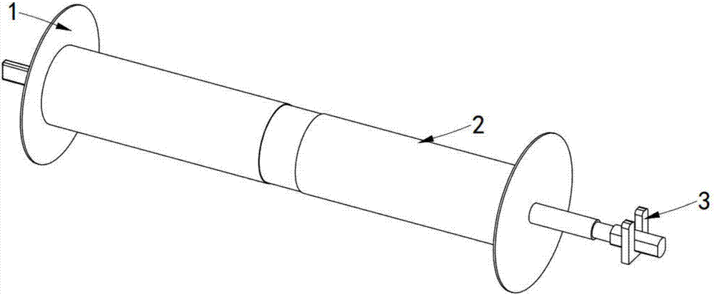
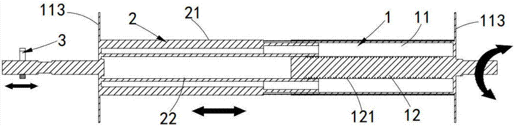
[0032] like figure 1 and figure 2 As shown, a split telescopic roller, including:

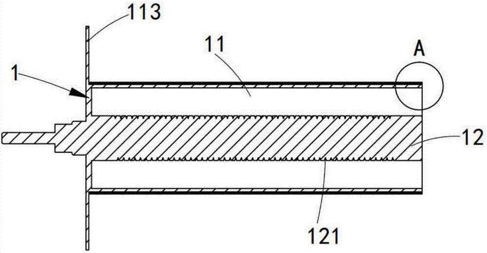
[0033] The first roller 1, the first roller 1 is cylindrical, which includes a first cylinder portion 11 and a first shaft portion 12, the first cylinder portion 11 is open at one end and hollow in the middle, and the first cylinder portion 11 is hollow. A shaft portion 12 is disposed at the center of the circle through the first cylindrical portion 11, and the first shaft portion 12 is solid;

[0034] The second roller 2, the second roller 2 is cylindrical, and it includes a second cylinder portion 21 and a second shaft portion 22, the second cylinder portion 21 is open at one end and hollow in the middle, and the second cylinder portion 21 is hollow. The second shaft part 22 is arranged at the center of the circle through the second cylinder part 21, and the second shaft part 22 is hollow;

[0035] The second cylinder portion 21 is concentrically slidably sleeved with the first cylinder p...


PUM


Abstract

The invention discloses a split telescopic roller, by dividing the roller into a first roller and a second roller, by using the first shaft part in the first roller and the second shaft part in the second roller For screw connection, when the first roller rotates, the second roller does not rotate, relying on the thread fit, the second roller moves to the outside, so that the whole roller is elongated and the length of the roller is changed. On the contrary, the first roller The roller is reversed, the second roller moves to the inside, and the roller is shortened as a whole, which solves the technical problem that the length of the roller cannot be adjusted, and realizes the telescopic adjustment of the roller.

Description

[0001] machine technology [0002] The invention relates to the technical field of textile rollers, in particular to a split telescopic roller. Background technique [0003] The roller is a cylindrical part, which is divided into driving and driven rollers. It is widely used in various transmission systems such as rotary screen printing machines, digital printers, conveying equipment, papermaking and packaging machinery, and is usually made of seamless steel pipes. Widely used in industries such as steel, metallurgy, coal, cement, power generation, chemical fertilizers, grain depots and ports. The use of rollers in the textile industry is also increasing year by year. Textile printing and dyeing is an important part of textiles. The demand for rollers Whether it is in textile printing and dyeing, drying or other technical fields, the demand for roller technology is also increasing. [0004] The traditional roller is set on both sides of the middle roller, and its length is fi...

Claims


Application Information

Patent Timeline
Patent Type & Authority Applications(China)
IPC IPC(8): B65H75/24
CPCB65H75/241B65H2701/53
Inventor 王会文
Owner 长兴夹浦正大纺织有限公司
Why Eureka
Try Eureka