Thread trimming mechanism of sewing machine

A thread trimming mechanism and sewing machine technology, applied to the thread cutting mechanism, sewing machine components, sewing equipment, etc. For problems such as high requirements, achieve the effect of stable driving process, improved coordination stability, and low coordination requirements

Active Publication Date: 2017-12-01
ZHEJIANG ZOJE SEWING MACHINE
View PDF10 Cites 2 Cited by
  • Summary
  • Abstract
  • Description
  • Claims
  • Application Information

AI Technical Summary

Problems solved by technology

[0004] Although the above-mentioned thread trimming mechanism can realize the automatic cutting of sewing thread, it also has some shortcomings: the connection between the swing bar and the thread trimming cam is realized by the cooperation of the slide block and the chute, and the chute is opened on the thread trimming cam. If the thread trimming cam can drive the pendulum to move when the chute cooperates with the slider, then the chute cannot be a straight groove or a traditional circular groove, but must have multiple corners or It is a special-shaped chute with angle change, so the cooperation between the pendulum bar and the thread trimming cam is very demanding. During installation, it must be ensured that the slider on the pendulum bar is facing the chute so that the thread trimming cam and the pendulum can be smoothly realized. Linkage of the rod, a slight deviation will cause the slider to fail to insert into the chute, resulting in idling of the thread trimming cam

Method used


Image

  • Thread trimming mechanism of sewing machine
  • Thread trimming mechanism of sewing machine
  • Thread trimming mechanism of sewing machine

Examples


Embodiment 1

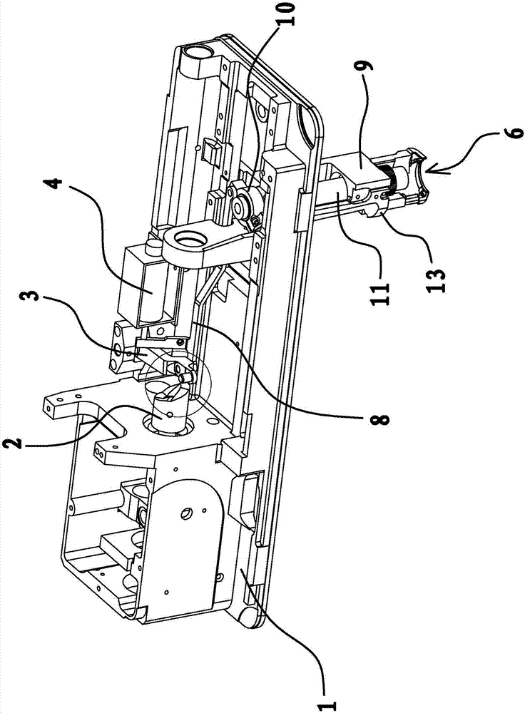
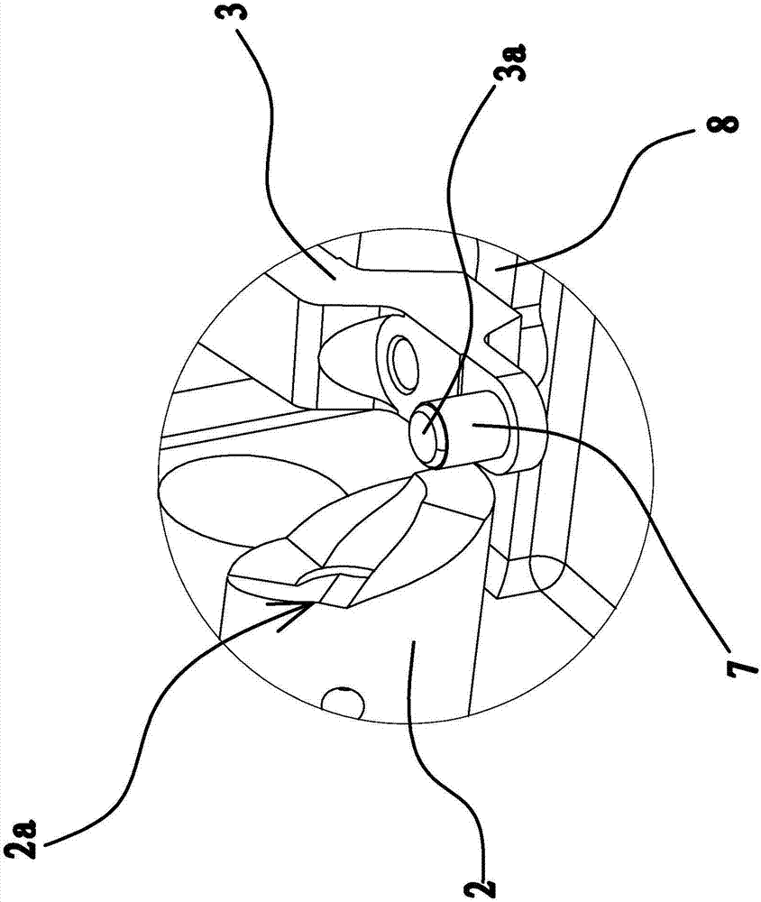
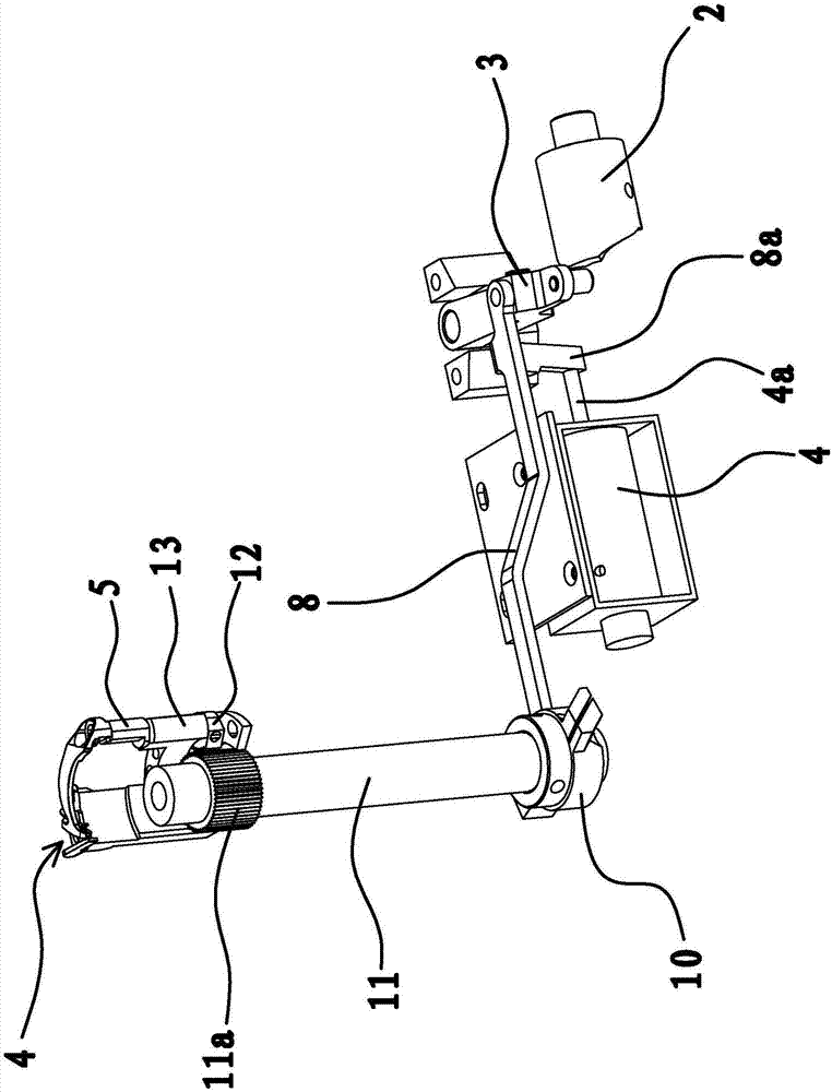
[0037] Such as figure 1 , figure 2 and image 3 As shown, a thread trimming mechanism of a sewing machine comprises a thread trimming cam 2 connected to the motor of the sewing machine, a swing bar 3 hinged on the lower side of the table top 1 of the sewing machine, and a swing bar arranged on the bottom side of the table top 1 of the sewing machine A driver, a pull rod 8, and a thread cutter 6 arranged on the upper side of the table top 1 of the sewing machine. The swing rod 3 is located between the thread trimming cam 2 and the swing rod driver. A swing rod seat is fixed on the lower side of the platen 1 close to the thread trimming cam 2. One end of the swing rod 3 is hinged on the swing rod seat. The other end of the swing rod 3 There is a protruding positioning head 3a on the upper side of one end, and a rolling sleeve 7 is provided outside the positioning head 3a. One end of the pull rod 8 is fixedly connected with the swing rod 3, and the other end of the pull rod 8...

Embodiment 2

[0048] The structure and principle of this embodiment are basically the same as that of Embodiment 1, the difference is that: Figure 8 As shown, in this embodiment, the transmission structure includes a driving gear 15, a transmission gear 12 and a thread cutting shaft 5, the driving gear 15 is arranged on the underside of the table 1 of the sewing machine and the driving gear 15 can rotate relative to the table 1 , The side of the driving gear 15 has a connecting lug 15a, and one end of the pull rod 8 is connected to the connecting lug 15a. The thread cutting moving shaft 5 is worn on the knife rest 9, and the lower end of the thread cutting moving shaft 5 is positioned at the lower side of the platen 1, and the transmission gear 12 is fixed on the lower end of the thread cutting moving shaft 5 and meshes with the drive gear 15. The upper end of thread cutting moving shaft 5 is fixed with 6 seats of thread cutter, and thread cutter 6 is fixed on 6 seats of thread cutter.

...

Embodiment 3

[0051] The structure and principle of this embodiment are basically the same as that of Embodiment 1, the difference is that: Figure 9As shown, in this embodiment, the transmission structure includes a connecting rod 16 and a thread-cutting moving shaft 5. The thread-cutting moving shaft 5 is installed on the tool holder 9, and the lower end of the thread-cutting moving shaft 5 is located on the lower side of the table 1. One end of the connecting rod 16 is fixed with the lower end of the thread cutting moving shaft 5 , and the other end of the connecting rod 16 is connected with an end of the pull bar 8 .

[0052] Because one end of the pull rod 8 is connected with one end of the connecting rod 16, and the other end of the connecting rod 16 is fixed with the lower end of the thread cutting moving shaft 5, the thread cutting moving shaft 5 can rotate relative to the knife rest 9 again, so it can be used as a swing lever 3 When the thread trimming cam 2 swings and drives the p...


PUM


Abstract

The invention provides a thread trimming mechanism of a sewing machine and belongs to the technical field of machines. The problem that the cooperative stability of an existing tread trimming mechanism of the sewing machine is poor is solved. The thread trimming mechanism of the sewing machine comprises a thread trimming knife, a swing rod driving piece, a swing rod and a thread trimming cam, wherein the swing rod is hinged to the sewing machine, and the thread trimming cam can rotate. The swing rod is located between the thread trimming cam and the swing rod driving piece, a transmission structure is arranged between the swing rod and the thread trimming knife, and the transmission structure can drive the thread trimming knife to swing and trim thread when the swing rod swings. The thread trimming cam is in a sleeve shape or in a columnar shape, a cam surface is arranged at one end of the thread trimming cam, the swing rod abuts against the cam surface, and when the thread trimming cam rotates, the swing rod can swing around the hinged point under the action of the cam surface.

Description

technical field [0001] The invention belongs to the technical field of machinery and relates to a sewing machine, in particular to a thread trimming mechanism of the sewing machine. Background technique [0002] Sewing machines are widely used in industries such as garment making and textiles. After the sewing machine sews the cloth, the sewing thread needs to be cut off. In the earlier traditional sewing machines, due to the low degree of automation, most of them were not equipped with a special thread cutting mechanism. When the fabric was sewn, the thread was cut manually by the user using scissors and other tools. And along with the continuous advancement of science and technology, the degree of automation of industrial sewing machines is getting higher and higher, and existing industrial sewing machines are basically equipped with automatic thread trimmers accordingly. Column type sewing machine is a kind of in sewing machine, and column type sewing machine mostly stil...

Claims


Application Information

Patent Timeline
Patent Type & Authority Applications(China)
IPC IPC(8): D05B65/00
CPCD05B65/00
Inventor 易相瑞鲍增金李健鹏严海军黄贤木楼俏军
Owner ZHEJIANG ZOJE SEWING MACHINE
Why Eureka
Try Eureka