Method for uniformly polishing optical device

A uniform technology for optical devices, applied in grinding/polishing equipment, grinding/polishing safety devices, working carriers, etc., can solve problems such as edge collapse, uneven flatness of optical devices, and unguaranteed product uniformity, etc., to achieve The effect of eliminating edge collapse, reducing the difficulty of fitting, and small friction coefficient

Active Publication Date: 2018-02-13
台州市正大光学有限公司
View PDF10 Cites 1 Cited by
  • Summary
  • Abstract
  • Description
  • Claims
  • Application Information

AI Technical Summary

Problems solved by technology

[0002] In the process of polishing optical devices, the uniformity and flatness of optical devices are the most important parameters that affect the quality of finished products. Therefore, the corner of the optical device at the outer periphery will go through a longer grinding path, so that the flatness of the same optical device after grinding will be different, that is, the edge collapse. In this case, the uniformity of the product cannot be guaranteed.

Method used


Image

  • Method for uniformly polishing optical device
  • Method for uniformly polishing optical device
  • Method for uniformly polishing optical device

Examples


Embodiment 1

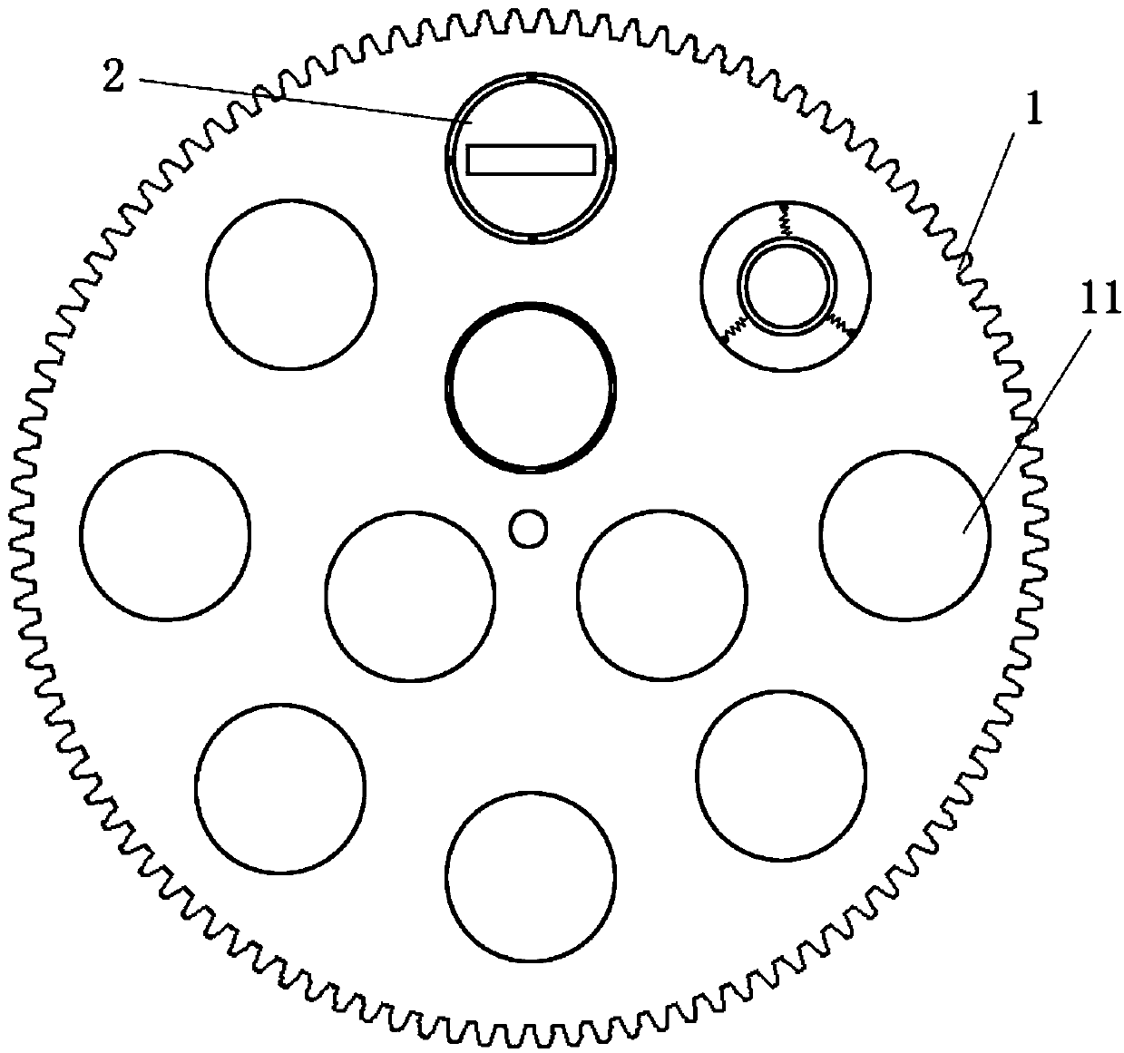
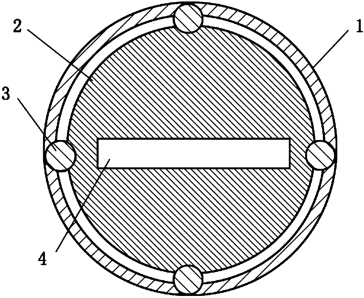
[0028] Such as figure 1 As shown, this embodiment is composed of a star wheel 1 and a processing cavity 2. The star wheel 1 is provided with a grinding hole 11, and the grinding hole 11 rotates around the center of the star wheel 1 during the grinding process. figure 2 It is a schematic diagram of the coordination of the planetary wheel 1 and the machining cavity 2. The planetary wheel 1 is provided with an annular raceway that matches with the ball 3, and the other end of the ball 3 is set in the notch of the machining cavity 2 (also can be set In a circular ring raceway), and the star wheel 1 does not touch the processing cavity 2, the processing cavity 2 is provided with a rectangular station 4, when contemporary workpieces are placed in the station for polishing, the star wheel 1 follows the polishing machine The driving gear rotates, because there is friction between the machining part and the grinding disc that prevents the machining part from rotating in the rotation dire...

Embodiment 2

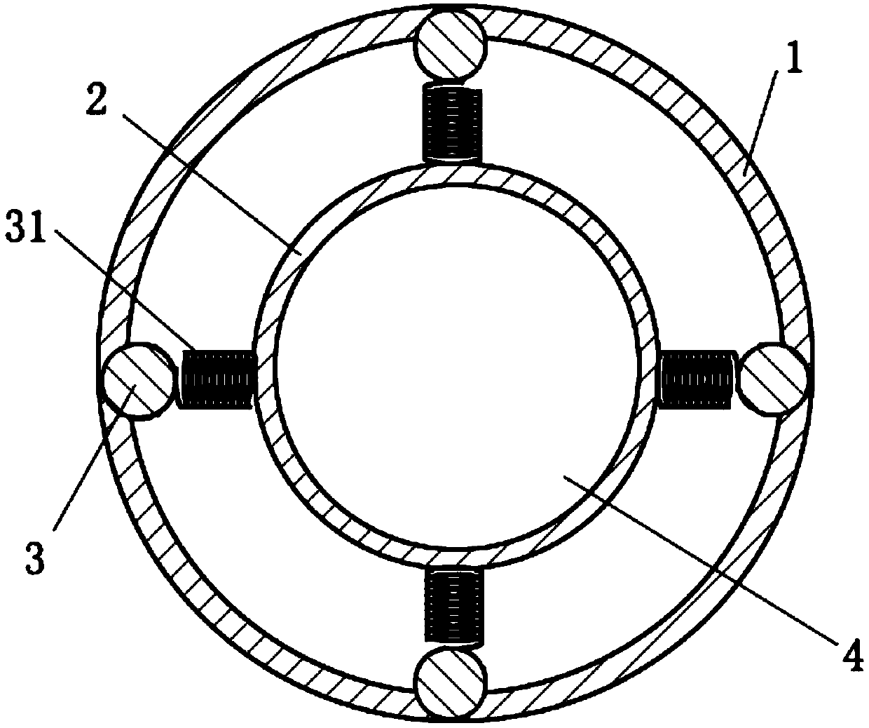
[0034] Such as image 3 As mentioned, this embodiment is basically the same as Embodiment 1, the difference is that the processing cavity 2 and the ball 3 are connected by an elastic member 31, wherein the natural length of the elastic member 31 is equal to the interval between the processing cavity 2 and the ball 3, thereby reducing the processing Matching requirements between cavity 2 and ball 3. When the grinding starts, the machining cavity is shifted relative to the center of the planetary wheel due to uneven force, so that the positions of the substitutive workpieces are shifted in different parts and the grinding is carried out on different paths.

Embodiment 3

[0036] Such as figure 1 As shown, the star wheel 1 is in direct contact with the processing cavity 2, and a lubricating layer is provided between the two. The lubricating layer can be alkyd resin, epoxy resin or acrylic resin, or a little less than 5% metal can be added to the above materials Oxide to increase wear resistance.


PUM


Abstract

The invention relates to a method for uniformly polishing an optical device. The method comprises the steps of 1, putting a planetary wheel into a polisher; 2, putting the optical device into a machining cavity, wherein the machining cavity is formed in a polishing hole of the planetary wheel and can freely rotate relative to the polishing hole; 3, starting polishing, wherein the planetary wheel rotates with a driving wheel of the polisher and has the rotation speed w1, the machining cavity rotates with the planetary wheel and the optical device and has the rotation speed w2, and w1 is not equal to w2. According to the technical scheme, in the polishing process, the grinding paths which all parts of the optical device pass by are basically the same.

Description

Technical field [0001] The invention relates to a polishing process, in particular to a method for uniform polishing of optical devices. Background technique [0002] In the process of optical device polishing, the uniformity and flatness of the optical device are important parameters that affect the quality of the finished product. When the existing planetary wheel is polished in the polishing machine, the optical device will be with the planetary wheel. Rotation, so the corners of the optical device at the outer circumference will go through a longer grinding path, so that the same optical device will have uneven flatness after grinding, that is, collapse. In this case, the uniformity of the product cannot be guaranteed. Summary of the invention [0003] The technical problem to be solved by the present invention is to provide a method that can uniformly polish the optical device, so that the polishing path of each part of the optical device is basically the same during the poli...

Claims


Application Information

Patent Timeline
Patent Type & Authority Applications(China)
IPC IPC(8): B24B37/30B24B55/00
CPCB24B37/30B24B55/00
Inventor 陆海锋
Owner 台州市正大光学有限公司
Why Eureka
Try Eureka