Motor rotor penetrating device

A technology of rotor and moving device, which is applied in the direction of adjusting/balancing rotor, manufacturing stator/rotor body, etc., can solve the compression damage of stator iron core and slot wedge, stator iron core slot wedge damage and falling off, stator iron core or motor rotor compression Deformation damage, etc.

Pending Publication Date: 2021-09-10
HUANENG TAICANG POWER GENERATION CO LTD
View PDF2 Cites 1 Cited by
  • Summary
  • Abstract
  • Description
  • Claims
  • Application Information

AI Technical Summary

Problems solved by technology

In the subsequent installation of accessories, if the motor rotor needs to be lifted on one side, the support of the motor rotor in the motor stator bore will all be concentrated on a small area at the end of the stator core, which w

Method used


Image

  • Motor rotor penetrating device
  • Motor rotor penetrating device
  • Motor rotor penetrating device

Examples


Embodiment 1

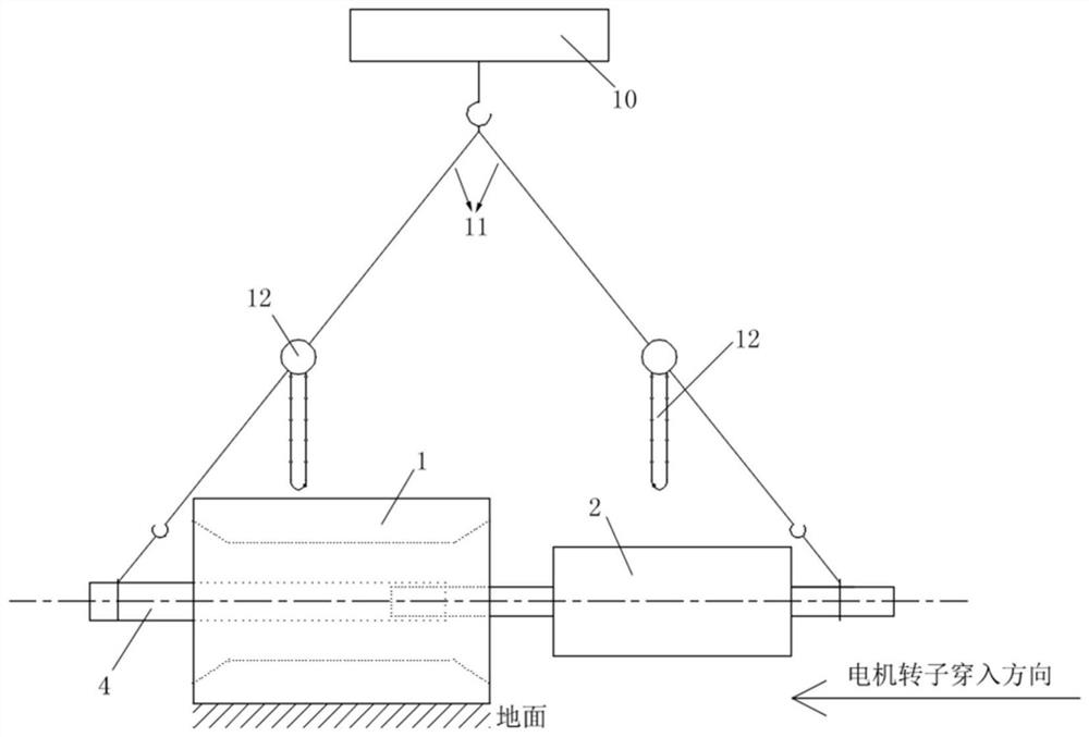
[0041] During the existing motor overhaul process, such as figure 1 As shown, the motor rotor 2 is hoisted by using the workshop crane 10 and the wire rope 11, and the motor rotor 2 is moved axially by jogging the workshop crane 1, so that the motor rotor 2 penetrates the motor stator 1, and the chain hoist 12 on the wire rope 11 is used to move the motor rotor 2. Adjust the level of the motor rotor 2 during the movement of the rotor 2. However, there are many certainties and deficiencies in the existing hoisting and threading back technology.

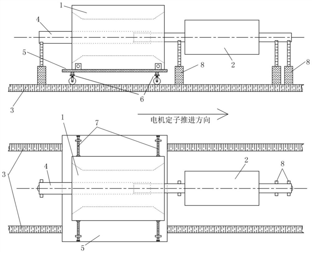
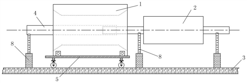
[0042] The application provides a motor through the rotor device, the side view and the top view are as follows figure 2 As shown, it includes a guide rail 3, a dummy shaft sleeve 4, a stator moving device 5 and a rotor supporting device, the stator moving device 5 moves back and forth along the guide rail 3, and the rotor supporting device is used to support the motor rotor 2; the stator moving device 5 includes a storage plate and ...


PUM


Abstract

The invention relates to a motor rotor penetrating device. The device comprises a guide rail, a dummy shaft sleeve, a stator moving device and a rotor supporting device; the rotor supporting device is used for supporting a motor rotor; the stator moving device comprises an object placing plate and a moving assembly; the moving assembly moves back and forth along the guide rail; a horizontal adjusting mechanism is arranged between the moving assembly and the object placing plate; a motor stator is placed on the object placing plate; a limiting and positioning mechanism is arranged on the object placing plate; and the rotor supporting device comprises a plurality of supporting frames, and the arrangement positions and the heights of the supporting frames can be adjusted. According to the motor rotor penetrating device, the motor rotor is supported by the supporting frames and the height of the motor rotor is adjusted, so that the central lines of the motor stator and the motor rotor can be aligned, the motor stator is driven by the stator moving device to move along the guide rail, and the motor rotor can easily penetrate into the motor stator, and collision and abrasion between the motor stator and the motor rotor are avoided, and structural damage of the motor stator and the motor rotor is effectively prevented.

Description

technical field [0001] The invention relates to the technical field of motor maintenance, in particular to a motor through-rotor device. Background technique [0002] In the traditional large-scale motor overhaul process, the back-piercing process of the large-scale motor rotor usually needs to be hoisted with the help of workshop cranes, such as a turbo-generator shaft core-threading device disclosed in Chinese patent CN207265842U and a shaft core-piercing device disclosed in Chinese patent CN107204690B. Core pulling method for large motor maintenance. Huaneng Taicang Power Plant generally uses workshop cranes and dummy shaft sleeves to cooperate with hoisting and re-threading of the motor rotor during the motor maintenance process. [0003] The operation process is as figure 1 shown. Put the motor stator flat on the ground of the factory building, put the dummy shaft sleeve on the shaft of the motor rotor, and the dummy shaft sleeve first penetrates into the motor stato...

Claims


Application Information

Patent Timeline
IPC IPC(8): H02K15/02H02K15/16
CPCH02K15/02H02K15/16
Inventor 黄鹏
Owner HUANENG TAICANG POWER GENERATION CO LTD
Why Eureka
Try Eureka