Eureka AIR delivers breakthrough ideas for toughest innovation challenges, trusted by R&D personnel around the world.

Crash barrier with buffer performance

A technology of anti-collision barriers and performance, which is applied in the direction of roads, road signs, traffic signals, etc., can solve the problems of ineffective traffic warning, weak anti-collision effect of anti-collision barriers, and easy to be moved, so as to protect life The effect of property safety, reducing the probability of casualties, and facilitating maintenance and repair

Inactive Publication Date: 2017-12-01
SHENYANG JIANZHU UNIVERSITY
View PDF0 Cites 14 Cited by
  • Summary
  • Abstract
  • Description
  • Claims
  • Application Information

AI Technical Summary

Problems solved by technology

[0007] Aiming at the problems existing in the prior art, the present invention provides an anti-collision barrier with cushioning performance, which absorbs the energy generated by the impact through deformation, and forces the out-of-control vehicle to change direction to the greatest extent and return to the normal driving direction. Prevent the vehicle from rushing out of the road, effectively protect the safety of the vehicle and passengers, reduce the probability of loss caused by the collision accident, control the loss caused by the collision to the greatest extent, and effectively reduce the probability of casualties and economic losses, etc. It solves the problem that the anti-collision effect of the existing anti-collision barrier is not strong, it is easy to deform after being hit, it is easy to be moved, and it cannot effectively play the role of traffic reminder

Method used


Image

  • Crash barrier with buffer performance
  • Crash barrier with buffer performance
  • Crash barrier with buffer performance

Examples


Embodiment

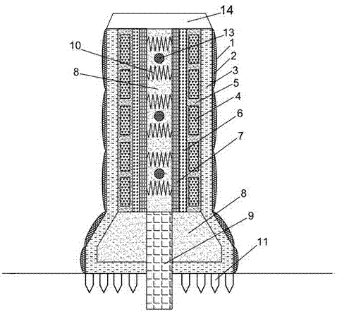
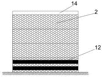
[0026] Such as Figure 1-4As shown, the anti-collision barrier with cushioning performance mainly includes protective cover 1, polyurethane rubber 2, anti-collision steel plate 3, energy-absorbing buffer material 4, high-damping concrete filling layer 5, anti-collision cushion 6, ultra-high toughness concrete 7. Sand 8, high-strength crack-resistant concrete column 9, spring shock absorber 10, high-strength gripping steel nails 11, fluorescent reflective strips 12, horizontal connecting steel pipes 13, capping top layer 14, steel pipe sleeves 15 and nuts 16, The structure of the anti-collision barrier with cushioning performance includes a barrier body and a base. The symmetrical structure is preferred for the barrier body. From the middle to both sides, there are spring shock absorbers 10, sand 8, ultra-high toughness concrete 7, and anti-collision barriers. Cushion pad 6, energy-absorbing buffer material 4, high-damping concrete filling layer 5, anti-collision steel plate 3,...


PUM


Abstract

The anti-collision barrier with cushioning performance adopts an axisymmetric structure. The outermost side is provided with a protective cover, the inner side of the protective cover is provided with polyurethane rubber, the inner side of the polyurethane rubber is provided with anti-collision steel plates, and the inner part of the anti-collision steel plate is the fence part and The base part and the column body part include a high-damping concrete filling layer set on the inner side of the anti-collision steel plate, and energy-absorbing buffer materials are arranged between the high-damping concrete filling layers, and an anti-collision cushion is arranged on the inner side of the high-damping concrete filling layer, and the anti-collision The inner side of the buffer pad is provided with ultra-high toughness concrete, and the inner side of the ultra-high toughness concrete has sand, and multiple spring dampers and horizontal connecting steel pipes are arranged in the sand in the column body part; the center of the base part is equipped with a high-strength The anti-crack concrete column is embedded in the ground, and sand is arranged between the anti-collision steel plate of the base part and the high-strength anti-crack concrete column. The invention has the advantages that the anti-collision barrier has strong anti-collision ability, high anti-deformation ability and high stability, and can effectively protect accidents such as collisions.

Description

technical field [0001] The invention relates to an anti-collision barrier, which belongs to the field of road traffic safety facilities, in particular to an anti-collision barrier with cushioning performance. Background technique [0002] Anti-collision barriers are a very common road traffic safety device. They are widely used in some dangerous areas, such as road turns, exits and entrances, and roads with high speeds, which are very dangerous. Necessary traffic safety infrastructure. At the same time, the anti-collision barrier is also a safety facility installed parallel to the road on both sides of the road or in the central divider, which can prevent abnormal driving vehicles from crossing the road or crossing the central divider due to driver error or other reasons. In the event of traffic accidents in the opposite lane, it protects the safety of pedestrians, buildings, drivers and occupants on the roadside, and at the same time, it can induce the driver's sight, incr...

Claims


Application Information

Patent Timeline
Patent Type & Authority Applications(China)
IPC IPC(8): E01F15/02E01F9/619E01F9/669
CPCE01F15/08E01F9/619E01F9/669E01F15/083E01F15/085E01F15/086
Inventor 张延年杨森
Owner SHENYANG JIANZHU UNIVERSITY
Why Eureka
Eureka Blog
Learn More