
Triaxial modularized dry type vacuum pump

A technology of dry vacuum pump and shaft module, applied in the direction of rotary piston pumps, pumps, rotary piston/swing piston pump components, etc., can solve problems such as dead angle, corrosion, equipment failure, etc., and achieve short distance and high energy consumption , the effect of air flow straight through

Active Publication Date: 2017-12-01
ELIVAC COMPANY
View PDF6 Cites 14 Cited by
  • Summary
  • Abstract
  • Description
  • Claims
  • Application Information

AI Technical Summary

Problems solved by technology

[0005] The existing multi-stage Roots vacuum pumps and claw vacuum pumps on the market only use a pair of synchronous gears, the impellers are coaxial and rotate in opposite directions, so that the air intake and exhaust directions of each pump chamber along the axial direction are Consistent, so that the gas flow from one vacuum chamber to the next vacuum chamber must pass through two 180° bends, and there is a dead angle of gas discontinuity at the bend, because the air flow will form a dead angle, for high boiling point organics , the gas will liquefy and solidify during the compression process. For dust, it is easy to get stuck in the bending and mechanical dead corners. If the corrosive gas will accumulate at this concentration, it will cause severe corrosion and eventually cause equipment failure. Therefore, multi-stage Luo The vacuum pump is only suitable for the process of clean gas

Method used


Image

  • Triaxial modularized dry type vacuum pump
  • Triaxial modularized dry type vacuum pump
  • Triaxial modularized dry type vacuum pump

Examples


Embodiment Construction

[0031] Embodiments of the technical solution of this embodiment will be described in detail below in conjunction with the accompanying drawings. The following embodiments are only used to illustrate the technical solution of this embodiment more clearly, so they are only examples, and should not be used to limit the protection scope of this embodiment.

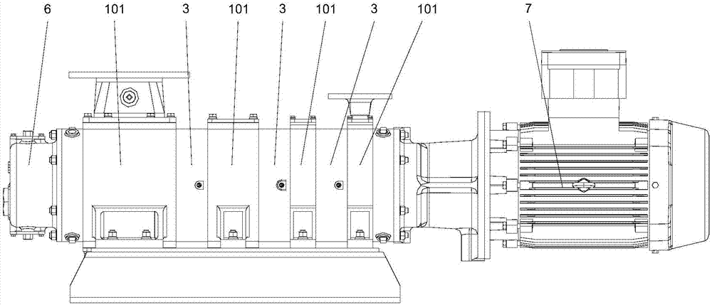
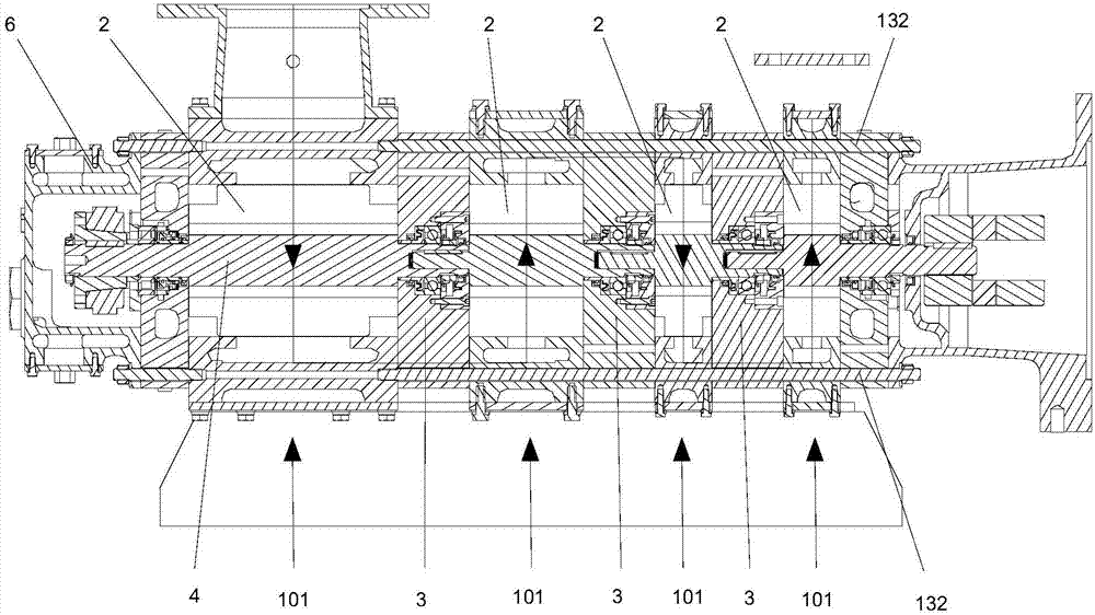
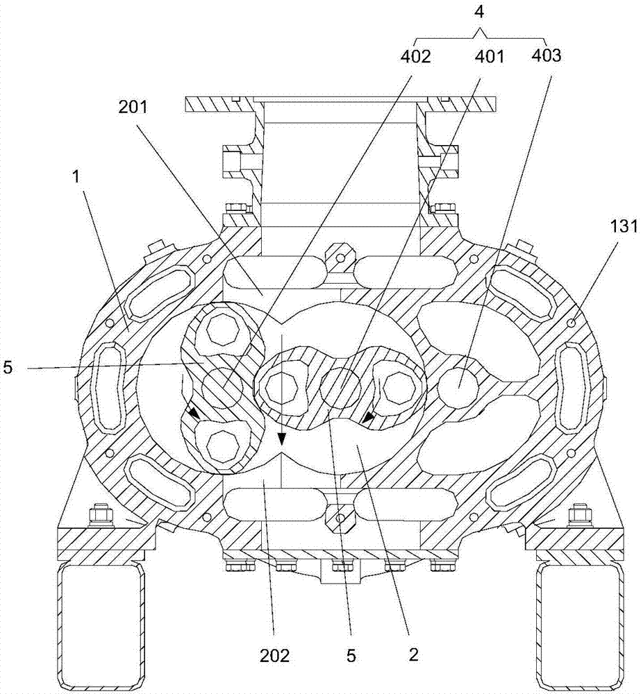
[0032] Such as Figure 1-Figure 7 As shown, the present invention provides a three-axis modular dry vacuum pump, which includes a pump body 1, and the pump body 1 is composed of multi-stage pump body units 101 in series, and each stage of the pump body unit 101 is correspondingly provided with a first-stage pump chamber 2 , Adjacent pump body units 101 are connected by partitions 3 , and the pump chambers 2 are separated by partitions 3 .

[0033] refer to Figure 2-Figure 4 One side of each pump chamber 2 is provided with a suction port 201, and the other side of each pump chamber 2 is provided with a discharge port 202. T...


PUM


Abstract

The invention discloses a triaxial modularized dry type vacuum pump. The triaxial modularized dry type vacuum pump comprises a pump body, wherein a multistage pump cavity is arranged in the pump body; a suction end opening is formed in one side of the pump cavity at each stage; an exhaust end opening is formed in the other side of the pump cavity at each stage; the exhaust end opening of the adjacent front-stage pump cavity communicates with the suction end opening of the adjacent rear-stage pump cavity; a middle pump shaft, a first side pump shaft and a second side pump shaft which are parallel are arranged in the pump cavity at each stage; each pump shaft of the adjacent front-stage pump cavity is in one-to-one correspondence with each pump shaft of the adjacent rear-stage pump cavity; the three pump shafts of the pump cavity at each stage rotate at the same speed, and the first side pump shaft and the second side pump shaft are reverse in rotation direction; paired rotors are arranged in the pump cavity at each stage; paired rotors of pump cavities at odd stages are separately connected on the middle pump shafts and the first side pump shafts; and paired rotors of pump cavities at even stages are separately connected on the middle pump shafts and the second side pump shafts. According to the triaxial modularized dry type vacuum pump disclosed by the invention, gas circulates from the front-stage vacuum cavity to the rear-stage vacuum cavity to realize down-flow without bending, so that the dead corner that gas is discontinuous is completely solved.

Description

technical field [0001] The invention relates to the technical field of vacuum equipment, in particular to a three-axis modular dry vacuum pump. Background technique [0002] A vacuum pump refers to a device or device that uses mechanical, physical, chemical or physicochemical methods to pump air into a pumped container to obtain a vacuum. Generally speaking, a vacuum pump uses various methods to improve, generate and maintain a vacuum in a closed space. Vacuum device. [0003] The new vacuum pumps developed in recent years, such as scroll pumps, screw pumps, claw pumps, air-cooled Roots vacuum pumps, multi-stage Roots vacuum pumps, etc. are all continuous and efficient dry vacuum pumps (there is no sealing liquid in the pump cavity), from From the perspective of energy saving, emission reduction and environmental protection, dry vacuum pumps are the main trend of future development. [0004] Roots vacuum pumps and claw vacuum pumps are more adaptable than screw pumps in de...

Claims


Application Information

Patent Timeline
Patent Type & Authority Applications(China)
IPC IPC(8): F04C25/02F04C18/14F04C29/00
CPCF04C18/14F04C25/02F04C29/00F04C2240/50F04C2240/60F04C2240/80
Inventor 荣易
Owner ELIVAC COMPANY
Learn More