Rotary reversing valve

A technology of rotating reversing valve and spool, applied in sliding valve, multi-port valve, valve device, etc., can solve the problems of not being suitable for low-cost production and rapid use, unable to realize oil circuit reversing, and high requirements for oil circuit connection , to achieve the effect of facilitating rapid production, simple structure and low cost

Pending Publication Date: 2017-12-01
株洲嘉成科技发展股份有限公司
View PDF12 Cites 3 Cited by
  • Summary
  • Abstract
  • Description
  • Claims
  • Application Information

AI Technical Summary

Problems solved by technology

The realization of its reversing function is mainly determined by the sequential connection of the 8 through holes on the front and back of the valve body with the liquid power end and the working load. It belongs to the reversing outside the valve body, and additional supporting facilities need to be added outside the valve body to realize the reversing Function, large use area, high cost. When the same group of through holes connected to the working load are connected to the oil supply port at the same time, no matter how the valve core rotates, the reversing of the oil circuit cannot be realized. Therefore, the connection requirements for the oil circuit are also very high. High, not suitable for low-cost production and rapid application

Method used


Image

  • Rotary reversing valve
  • Rotary reversing valve
  • Rotary reversing valve

Examples


Embodiment 1

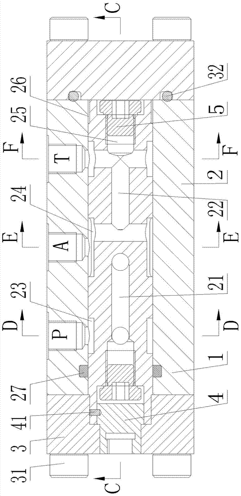
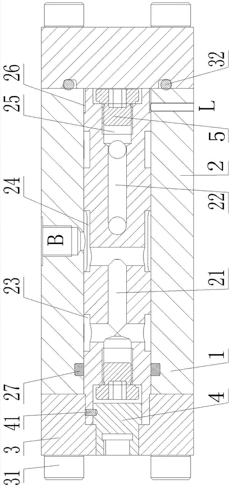
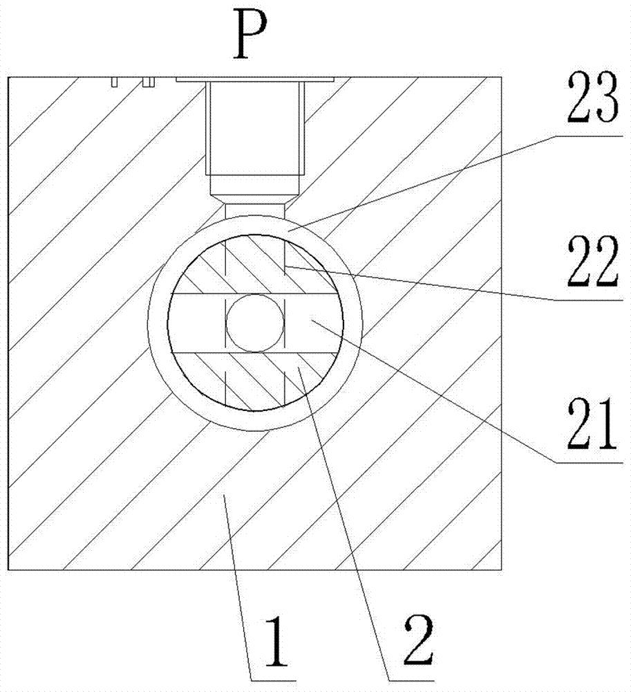
[0040] Taking the two-position four-way reversing valve as an example, from Figure 1 to Figure 5 It can be seen that the cross section of the valve body 1 of the present invention is square, and the working oil ports include oil port A and oil port B, and the oil port A and the oil port B are arranged on the center of the adjacent side walls of the valve body 1 and on the valve body 1. If the cross section is arranged at an included angle of 90°, there are two oil inlet passages 21 arranged symmetrically on the spool 2. The two oil inlet passages 21 share the blind hole 25 at the left end of the spool 2 on the longitudinal section of the spool. Two oil outlet passages 22 are symmetrically arranged on the valve core 2. The blind hole 25 at the right end of the common valve core 2 of the two oil outlet passages 22 is H-shaped on the longitudinal section of the valve core. The oil inlet passage 21 and the oil outlet passage 22 on the cross-section of the spool 2 are alternately ...

Embodiment 2

[0050] Take the three-position five-way reversing valve as an example, from Figure 6 to Figure 9 It can be seen that the cross section of the valve body 1 of the present invention is circular, and the working oil ports include the oil port A1, the oil port B1 and the oil port A2 arranged at an angle of 60° on the cross section of the valve body, and the oil inlet channel 21 There are two and symmetrically arranged on the spool 2, and the blind hole 25 at the left end of the common spool 2 of the two oil inlet passages 21 is H-shaped on the longitudinal section of the spool, and there are two oil outlet passages 22, which are symmetrically arranged on the spool 2 Above, the blind hole 25 at the right end of the common spool 2 of the two oil outlet passages 22 is H-shaped on the longitudinal section of the spool, and the oil inlet passage 21 and the oil outlet passage 22 are arranged at an angle of 60° on the cross section of the spool 2, There are four grooves 24 and they comm...

Embodiment 3

[0062] Take the two-position five-way reversing valve as an example, from Figure 10 to Figure 13 It can be seen that the working oil port of the present invention includes the oil port A3, the oil port B3 and the oil port A4 which are successively arranged at an angle of 60° on the cross section of the valve body, and there are three oil inlet passages 21 arranged in an annular array on the On the spool 2, three oil inlet passages 21 share the blind hole 25 at the left end of the spool 2, three oil outlet passages 22 are arranged on the spool 2 in an annular array, and the three oil outlet passages 22 share the blind hole 25 at the right end of the spool 2. The holes 25, the oil inlet passages 21 and the oil outlet passages 22 are arranged alternately at an angle of 60° on the cross section of the valve core 2, and there are six grooves 24 which communicate with the oil inlet passages 21 and the oil outlet passages 22 respectively. .

[0063] The rotation commutation process...


PUM


Abstract

The invention discloses a rotary reversing valve comprising a valve body, a valve core, two end covers and a connecting shaft. The valve core is arranged in the valve body, a main oil inlet P, work oil ports and a main oil outlet T are formed in the side wall of the valve body, and at least two oil inlet passages communicating with the corresponding work oil ports and the main oil inlet P and at least two oil outlet passages communicating with the corresponding work oil ports and the main oil outlet T are formed in the valve core. The connecting shaft is connected with the valve core to drive the valve core to rotate in the valve body so as to control communicating and reversing of an oil way, and the positions, corresponding to the main oil inlet P and the main oil outlet T, of the valve core are each provided with an annular groove. The oil inlet passages and the oil outlet passages are each in a right-angled-U shape on the longitudinal section of the valve core and communicate with the corresponding annular grooves and the corresponding work oil ports correspondingly. The oil inlet passages are arranged in an annular array mode on the cross section of the valve core, the oil outlet passages are arranged in an annular array mode on the cross section of the valve core, and the oil inlet passages and the oil outlet passages are arranged in an alternated mode in sequence on the cross section of the valve core. The rotary reversing valve is balanced in radial force and low in cost and belongs to intra-valve-body reversing.

Description

technical field [0001] The present invention relates to a rotary reversing valve. Background technique [0002] The reversing valve is a directional control valve with more than two flow forms and more than two oil ports. It is a valve that realizes the communication, cutting and reversing of hydraulic oil flow, as well as pressure unloading and sequential action control. In general, the hydraulic reversing valve controls the on-off of the oil passage inside the valve body by sliding the spool left and right, so as to control the movement direction of the actuator. In some construction machinery (such as hydraulic breaker, hydraulic pile driver, etc.), the frequency of reversing back and forth of the actuator is relatively high. If the reversing is still controlled by sliding the valve core left and right, the control technology requirements are relatively high. Because the spool itself has a certain inertia, and is in the state of acceleration and deceleration all the time...

Claims


Application Information

Patent Timeline
IPC IPC(8): F15B13/02F16K11/076F16K3/314
CPCF15B13/022F16K3/314F16K11/076
Inventor 彭彪
Owner 株洲嘉成科技发展股份有限公司
Why Eureka
Try Eureka