
Spring oil hydraulic system

A technology of hydraulic system and spring hole, which is applied in the direction of fluid pressure actuation system components, fluid pressure actuation devices, mechanical equipment, etc., can solve the problems of easy damage of bed and oil cylinder, high pressure of machine tool, and reduce maintenance rate , reduce pressure, and protect the effect of the machine tool

Inactive Publication Date: 2017-12-01
嘉兴和新精冲科技有限公司
View PDF3 Cites 0 Cited by
  • Summary
  • Abstract
  • Description
  • Claims
  • Application Information

AI Technical Summary

Problems solved by technology

[0002] The machine tool uses oil pressure to work, and the same oil pressure is used for cutting and dragging. The machine tool is under high pressure, and the bed and oil cylinder are also easily damaged.

Method used


Image

  • Spring oil hydraulic system

Examples


Embodiment Construction

[0011] In order to make the technical means, creative features, goals and effects achieved by the present invention easy to understand, the present invention will be further described below in conjunction with specific embodiments.

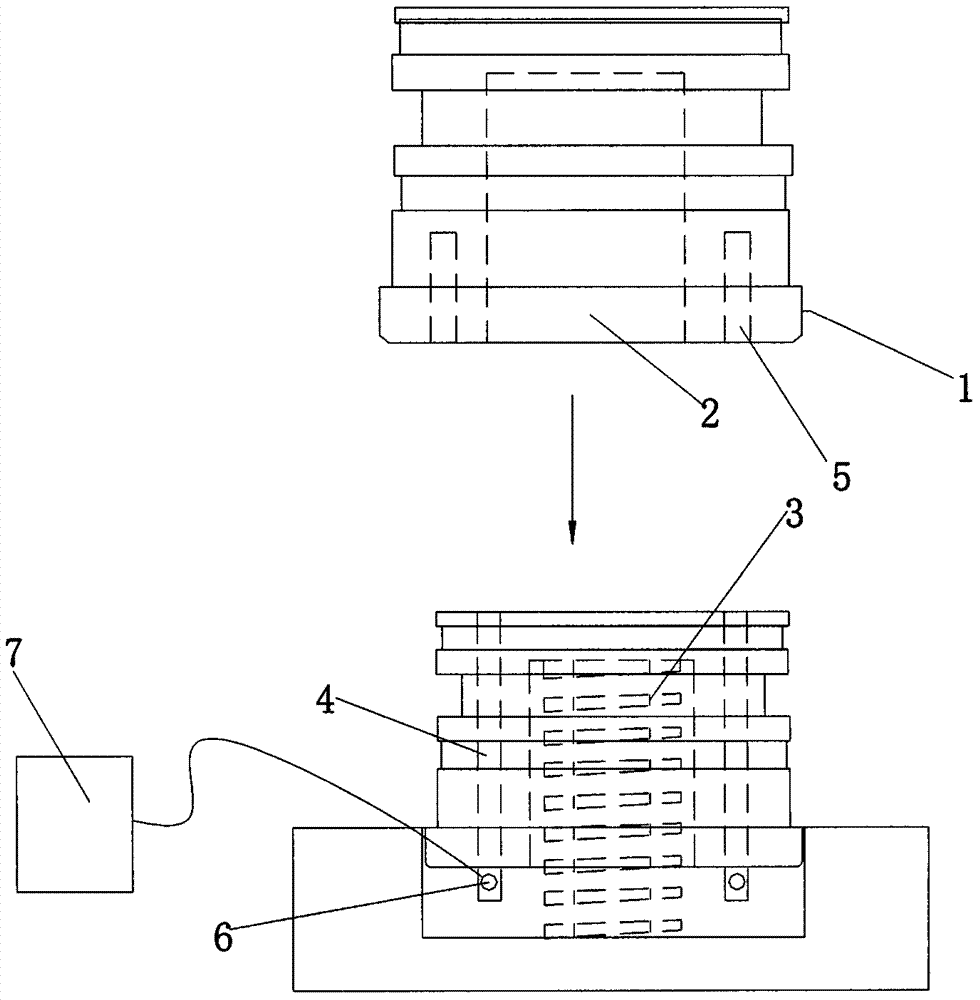
[0012] refer to figure 1 , the present embodiment adopts the following technical solutions: a spring oil pressure system, comprising an oil cylinder 1, a spring hole 2, a spring 3, a pressure reducing device 4, a pressure reducing hole 5, a pressure sensor 6 and a PLC controller 7, and the bottom of the oil cylinder 1 is provided with Spring holes 2 and decompression holes 5, the decompression holes are evenly distributed around the spring holes 2, a spring 3 is arranged in the spring holes 2, a decompression device 4 is arranged in the decompression hole, and the decompression device 4 is connected with the pressure sensor 6, The pressure sensor 6 is connected with the PLC controller 7 .

[0013] It should be noted that the bottom of the oil cyl...


PUM


Abstract

The invention discloses a spring oil hydraulic system. The spring oil hydraulic system comprises an oil cylinder, a spring eye, a spring, pressure-relief devices, pressure-relief holes, a pressure sensor and a PLC controller. The spring eye and the pressure-relief holes are formed in the bottom of the oil cylinder, the pressure-relief holes are evenly distributed in the periphery of the spring eye, and the spring is arranged in the spring eye; and the pressure-relief devices are arranged in the pressure-relief holes, the pressure-relief devices are connected with the pressure sensor, and the pressure sensor is connected with the PLC controller. According to the spring oil hydraulic system, pressure can be reduced, a machine tool is protected, and the maintenance rate of a machine tool station and the oil cylinder is decreased.

Description

technical field [0001] The invention relates to the technical field of machine tool accessories, in particular to a spring hydraulic system. Background technique [0002] The machine tool uses oil pressure to work, and the same oil pressure is used for cutting and dragging. The machine tool is under high pressure, and the bed and oil cylinder are also easily damaged. Therefore it is necessary to carry out some structural improvements to the oil cylinder of the existing machine tool. Contents of the invention [0003] Aiming at the deficiencies in the prior art, the purpose of the present invention is to provide a spring hydraulic system, which reduces the pressure, protects the machine tool, and reduces the maintenance rate of the bed and the oil cylinder. [0004] In order to achieve the above object, the present invention is achieved through the following technical solutions: a spring oil pressure system, including an oil cylinder, a spring hole, a spring, a decompressi...

Claims


Application Information

Patent Timeline
IPC IPC(8): F15B21/02
CPCF15B21/02
Inventor 高小林陈成
Owner 嘉兴和新精冲科技有限公司
Learn More